UKMARSBOT assembly details for original and version 1.3a boards: using either the Arduino Nano processor board or the Waveshare ESP32 S3 Nano processor board or the Cytron Maker Nano RP2040 processor board
Main PCB assembly
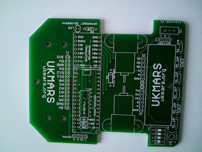
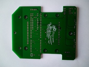
This is the original main printed circuit board top and bottom: identified by UKMARSBOT 20190804A on the edge.
Below is the v1.3a main printed circuit board top and bottom: identified by ukmars.org and V1.3a on the edge.
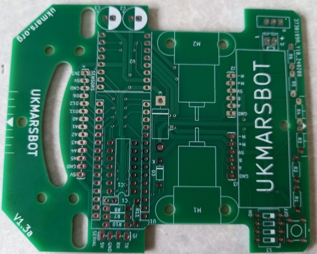
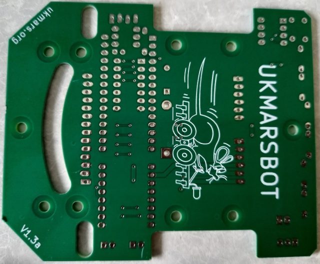
The V1.3a board has these differences from the original board :
- Three cut outs to allow the sensor boards to mount line photosensors closer to the centre of the robot
- The PCB LED on pin D13 and its R9 load resistor are replaced by 2 additional power smoothing capacitors
- The 2 holes for the battery holder elastic band have been removed
- The components that support the Bluetooth connection have been repositioned
BUILD SEQUENCE
The majority of the build is the same for both boards but differences will be pointed out as necessary
Solder the parts in order of height e.g. resistors, diodes, ceramic capacitor, switches and motor driver then IC then sockets/headers and big capacitors. The pictures below will show you where things need to go.
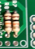
- Solder in resistors R1 to R6

Note that on the v1 version of the board, the R2 and R5 resistors have been offset to make soldering easier, and on the V1.3a board it is R2 and R3 that are offset

It is helpful if you put all of these resistors in place from the top of the board before you start to solder, as this will avoid you getting solder into the PCB holes next to the one you are soldering in. Check that you have the correct value resistors in each place before you solder them in. You may want to hold these resistors in place with some Blu Tack so that they do not fall out while you solder them on the bottom side of the board.
Do not worry if the ends of the resistors at the back edge of the board short out together e.g. between R1 and R2 or R2 and R3 etc up to R5 and R6, as they are connected anyway in the circuit. Clip off all the excess leads for each device as soon as you have soldered it in so that it does not get in the way of further soldering. If you are using the Cytron Maker Nano processor board you do not need to put in resistors R1, R2, R3, R4 and R5 but they will do no harm if they are there, but you do still need R6
If you are using the Arduino Nano processor, solder in R7 and R8 making sure that these 10K Ohm resistors which are mounted below the Arduino are close to the board. Note that the marking of the position of these varies slightly between the v1 and the v1.3a boards. If you are using the Waveshare ESP32 S3 Nano change R7 to be 33K ohms so as to reduce the battery voltrage to below 3.3.volts for the ESP32 input. If you are using the Cytron Maker Nano RP2040 processor board these two components should be left out
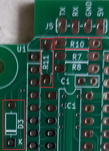
Now solder in the 2 diodes between the Arduino socket and the motor mounts. The larger one is to protect against the battery being connected the wrong way round, while the smaller one is used for the Bluetooth service (see blow). Make sure these are connected the right way round. The diagram is for the v1.3a board but the earlier board is similar with slightly different sized parts shown.
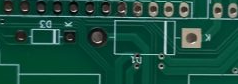
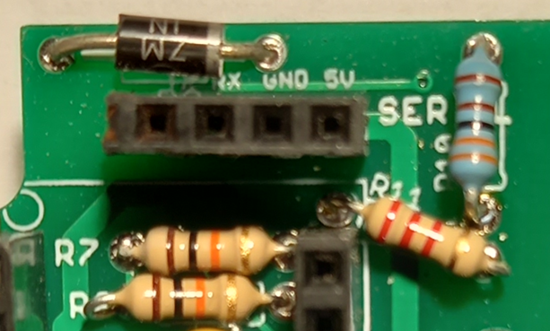
 If you plan to use an HC05 or HC06 or similar Bluetooth module for serial connection the v1 board has 2 extra resistors R10 and R11 and an extra diode D2. Note that on V1.3a these components are in a slightly different place and the diode is renamed as D3
Solder these 2.2K and 3.3K ohm resistors in as shown and then ensure that you put the diode in the right way round with the grey band at the end closest to the 3.3K resistor. Also add a 4 pin header for plugging the HC05 or HC06 module into, which if it has 6 pins should have one pin each side of the 4 way connector and oriented so that the 5v connection on the module aligns with the 5v shown on the board.
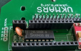
- Before you put the 15 way connectors in, add the 100nF capacitor C1 next to R8, then the encoder pulse doubler JC1 SN74HC86N. Make sure that the dent at one end of the device is at the end where the C7, R8 and R7 are located.
- If you are using either the Waveshare ESP32 S3 Nano or the Cytron Maker Nano processor board, cut the 15 way connector into a 3-way and an 11-way one then solder in the 3 way one at the end nearest the 4 hole serial socket, then leave a one pin gap and put the 11 way socket in the rest of the holes in the board. On the back of the board solder together the 5V and the adjacent 3.3V pins of the J1 sensor connector. This disables the 5V output from either of these boards and feeds the circuit positive supply from 3.3 volts instead.
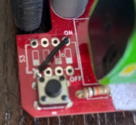
If you are using the Cytron Maker nano RP2040 don’t put in the 4-way DIP switch but put a connecting wire between the bottom left and the top right of the socket holes as shown here. Fo the Arduino or Waveshare ESP32 do put the 4 way DIP switch in as this will be an easy way to select up to 16 different programs to run