Skip to content
- The basic line sensor board is fixed to the main PCB with two M3 screws with a 10mm spacer between the main PCB and the sensor board, with the nuts on top.
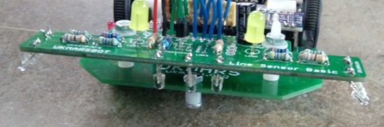
- Two sets of holes are provided for mounting sensor boards. Use the most suitable ones for your board. For the basic line follower sensor board this needs to be the front set, so that the LED and Phototransistors in the middle of the board are just ahead of the front of the main board.

- The M3 bolts can be metal or nylon
- Before fitting the sensor board you should add a skid to the front of the board, as it will be front heavy and we don’t want the LED and phototransistors to be too close to the ground. An M3 bolt with a 5mm spacer though the central hole at the front of the robot will make the robot level if you are using 32mm wheels. If you are using different sized wheels, adjust the bolt length and spacer size as necessary to get the ends of the lens on the central LED about 1cm from the ground.
