Main Printed Circuit Board (PCB)
The main printed circuit board for the robot is designed to hold the motors, battery and all the electronic components needed to make the robot work. The board implements a series of circuits that connect the various electronic parts. These circuits and their functions are described below:
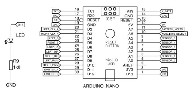
- The brain of the robot is an Arduino Nano microcontroller. It reads the switches and sensors and uses this information to control the power going to the motors and various indicators. This circuit shows the 30 connections to the Arduino Nano and to the indicator LED on Digital pin 13.
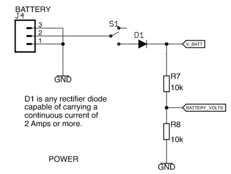
- This circuit shows the battery connector, the on off switch, the reverse polarity protection diode and the 2 resistors used to provide an input for measuring the battery voltage.
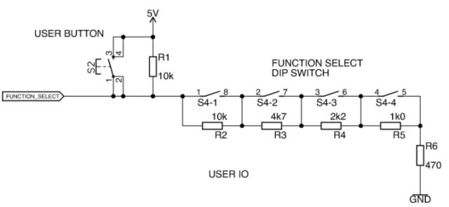
- This resistor ladder circuit allows us to use the 4 pole on off switch and the press button tactile switch to generate 16 distinct analogue values that can be read by just one pin on the Nano and then used to select different programs or functions within them.
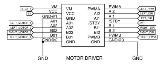
- This circuit shows the connections to the Sparkfun motor driver board. This board amplifies the small current available as an output from the microcontroller to a size which is able to power the motors. It also sets the direction in which the motor will rotate. Inputs PWMA and PWMB take a Pulse Width Modulated(PWM) signal from the microcontroller to set the speed of the motor, whilst A1 and A2 set the direction of motor A, and B1 and B2 set the direction of motor B
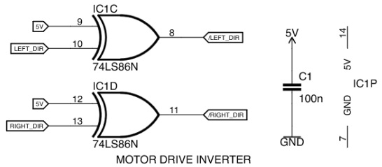
- These two logic gates provide an inverted version of the motor direction signal so that the motor direction can be set by just one output pin from the Nano instead of needing two for each motor. The other components shown are a smoothing capacitor on the power supply for the Nano and the power supply connections for IC1.
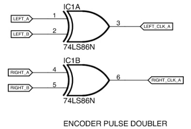
- These two logic gates on IC1 enable us to double the number of encoder pulses coming from the motors so as to increase the accuracy of the speed and position measurement.
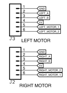
- These two connectors are the ones that make the connections to the motors. If you are not using encoders you only need to connect the motors to pins 5 and 6 on each of the 2 connectors
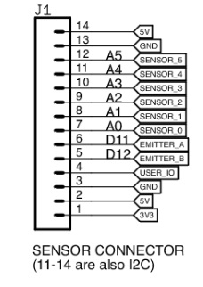
- This connector is used to feed power and signals to the sensor board, and to pass the returned sensor read values back to the microcontroller. Not all of the connections are needed for each sensor board
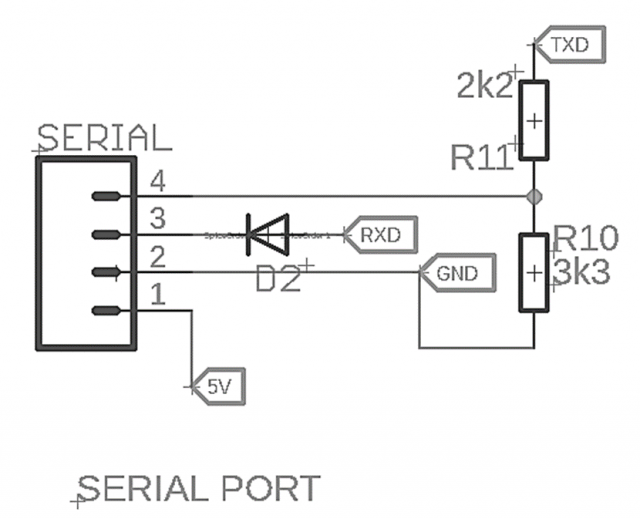
- This connector is used to enable a serial signal to be passed from the microcontroller to another device. This could be a serial cable or a serial transmission module or an HC05 or HC06 Bluetooth module so as to pass data to or from the robot to another computer. When used with an HC06 Bluetooth module, the 2 resistors reduce the transmit level to the required 3.3 volts and the diode allows the Arduino to still be programmed when the Bluetooth module is connected