
Building Guide:
Tools
The robot is designed to be built with a limited set of tools.
You will need the following:
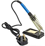
- A soldering iron with a small bit, plus solder
- A small pair of side cutters for clipping component leads and wires to length
- A small pair of pliers for holding parts and nuts while being tightened and optionally a long nosed pair.
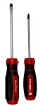
- Flat and cross head screwdrivers for tightening nuts and bolts
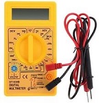
- A digital multi meter to measure voltages and resistance values. Typically available for about £5 on EBay


Parts
UKMARS Main Board PCB – versions 1.1 and 1.3a
Resistors – all 0.125 or 0.25 watt
| Part | Value | Note |
|---|---|---|
| R1 | 10k Ohm | R1 to R5 Not needed if using Cytron Maker Nano RP2040 board |
| R2 | 10k Ohm | |
| R3 | 4k7 Ohm | |
| R4 | 2k2 Ohm | |
| R5 | 1k0 Ohm | |
| R6 | 470 Ohm | Always needed |
| R7 | 10k Ohm | R7 and R8 Not needed if using Cytron Maker Nano RP2040 board |
| R8 | 10k Ohm | |
| R9 | 1k0 Ohm | only needed for the v1 main board but not for the 1.3 main board |
| R10 | 3k3 Ohm | only needed for bluetooth module |
| R11 | 2k2 Ohm | only needed for bluetooth module |
Capacitors
| Part | Value | Note |
|---|---|---|
| C1 | 100nF | (usually marked 104). |
| C2 | 470µF, 10V | For V1.3a board. Low height 12mm or less |
| C3 | 470µF, 10V | For V1.3a board. Low height 12mm or less |
C2 and C23 can be 10 Volt or 16 Volt parts with as large a capacitance as you can find so long as they will fit and not be more than 12mm high. Otherwise the USB lead will not fit.
Switches
| Part | Value | Note |
|---|---|---|
| S1 | SPDT slide or toggle | Check pin spacing |
| S2 | 6mm tactile button switch | |
| S3 | 4 pole dip switch | e.g. RS 122-2960, CPC SW05606, Rapid 80-0334 Not needed if using Cytron Maker Nano RP2040 board |
Diodes
| Part | Value | Note |
|---|---|---|
| D1 | 1N5401 | any 2A power rectifier |
| D2/D3 | 1N4148 | small signal diode (only needed for BT module) |
D2/D3 are the same part, marked differently the V1.1 and V1.3 bords
LED – For V1.1 board only
| Part | Value | Note |
|---|---|---|
| LED | any 3mm LED |
Encoder Pulse Doubler
| Part | Value | Note |
|---|---|---|
| IC1 | 74HC86 |
Motor driver board
| Part | Value | Note |
|---|---|---|
| U2 | Sparkfun TB6612FNG | 2 x 8 header pins soldered through |
Processor board
Normally the Arduino Nano with 2×15 header pins soldered in for coding in the Arduino environment. Alternatively, you can fit a Cytron Maker Nano RP2040 for coding in Python
Sockets
- Processor – Two 15 way single row headers. Rapid-online Order code: 19-0086.
- One 14 way single row header (J1) for sensor boards
- One 4 way single row header (J5) for Serial or Bluetooth
- Two 6 way headers (J2/J3) for the motors
- one 2 way or 3 way MALE header (J4) for the battery. Alternatively, solder the PP3 Battery connector (Rapid 18-0546) directly into the board.
Line Following Sensors
UKMARS Line Sensor PCB
Resistors
- R1, R8, R9 390Ὠ;
- R2 10KὨ;
- R3, R4, R5 68Ὠ;
- R6, R7, R10, R11 4.7KὨ. Can be 2k0 up to 4k7 depending on phototransistor choice
Transistor – Q1 – BC337-40 Bipolar NPN transistor- Rapid-online Order code: 50-3113
Capacitor – C1 100µF electrolytic – Rapid-online Order code: 11-3508
Indicator LEDs* – LED4, LED5 – any colour general purpose visible LED
Using Visible Light
Sensor Emitters – 3 x Truopto OSHR3131A-NO 3mm 3000mcd – Rapid-online Order code: 55-0066
Phototransistor – 4 x Vishay BPW85C 3mm – Farnell part no 104-5380
Using IR light
Sensor Emitters – Option a) 3 x Osram SFH409.
Phototransistor – Option a) 4 x Osram SFH309FA.
Line Sensor Half size (visible light)
Resistors – R1, 390Ὠ; R2 10KὨ; R3, R4, R5 68Ὠ; R6, R7, R10, R11 2.2K Ὠ R8, R9 1KὨ;
Transistor – BC337-40 Bipolar NPN transistor- Rapid-online Order code: 50-3113
Capacitor – C1 100µF electrolytic – Rapid-online Order code: 11-3508
Emitter LEDs – 3 x Truopto OSHR3131A-NO 3mm 3000mcd – Rapid-online Order code: 55-0066
Phototransistor – 4 x Vishay BPW85C 3mm – Farnell part no 104-5380 08
Indicator LEDs – any general purpose visible LED
Connector – 10 way single row male header- Rapid-online Order code: 54-5075
Wall Following Sensor Basic
Two Options: a) the IR version, b) the visible light version
Capacitor – C1 100µF electrolytic – Rapid-online Order code: 11-3508
**Resistors **
- R1, R2 390Ὠ;
- R3, R4, R5 1.8kὨ;
- R6 390Ὠ;
- R7 10KὨ;
- R8 33Ὠ;
- R9, R10, R11 33Ὠ;
Transistor – BC337-40 Bipolar NPN transistor- Rapid-online Order code: 50-3113
Infra Red Light Version
Sensor Emitter LEDs LED3, LED4, LED5 – 3 x Osram SFH4550 5mm Phototransistor – e.g. 3 x Vishay BPW85C 3mm – Farnell part no 104-5380 or BPW96B
Visible Light Version
Resistors Option
- R1, R2 390Ὠ;
- R3, R4, R5 1.0kὨ;
- R6 390Ὠ;
- R7 10KὨ;
- R8 33Ὠ;
- R9, R10, R11 10Ὠ;
Sensor Emitter LEDs – LED 3, LED 4, LED 5 – 3 x Vishay TLCR5800 5mm Phototransistors – e.g. 3 x Vishay BPW85C 3mm – Farnell part no 104-5380 or BPW96B
Motors and mounts
Motors – 2 x N20 12mm micro gearmotors. Suggested gear ratio is 20:1 but anything from 10:1 to 60 :1 is OK. If you want to use encoders you need one with the extended rear shaft. Pimoroni or Polulo have a good range e.g. the Pimoroni 20:1 extended shaft micro gearmotor
Motor mounts – These may be 3D printed or bought from Polulo, Kitronic, Pimoroni or Ebay. Note that there are several types available. See assembly notes
Wheels
The chassis is ideally suited to 2 x 32mm diameter wheels with 3mm D shaft centres. These may be 3D printed or bought with tyres from Polulo, Kitronic or Pimoroni. If you are 3D printing them you will need 25mm “O” rings to use as tyres, available on Ebay.
Battery – Any PP3 9Volt nominal rechargeable battery will do. NiMh ones (e.g. from B&Q) are heavier than the Lithium ion ones that can be recharged from a 5V USB supply (available on Ebay or Amazon) The Liter 9V 1200mAh one available on eBay is very good as it can be recharged with just a USB micro cable while on the robot and has capacity LEDs on it
Battery holder
for v1.1 board – Three metal paper clips and a small elastic band. For v1.3a board use Velcro on the board and the battery
Sensor Board Connector
The latest sensor boards plug directly into the J1 connector at the front of the board
Motor connector
Two options: 1) 6 x Dupont F to F connector leads (from Ebay) cut in half, or option 2) 2 x 6 way e.g. Molex wire to board connector 2.54mm. e.g. Farnell part no 1756789 plus crimp insets as in above item
Nuts & Bolts
Some commercial motor mounts will come with M2.5 bolts. These will fit the board directly. Other mounts, and the 3D printed versions will use M3 bolts. Depending on the motor mounts used you may need four M2.5 bolts and nuts for them. Otherwise, all the other nuts, bolts and spacers used are M3 size. If you use M3 bolts for the motor mounts you will need to slightly enlarge the motor mount holes in the main PCB to accommodate these, as they are current drilled for M2.5 bolts.
Two 20mm length bolts are used with 10mm spacers to hold the line follower sensor board in place.
One 12mm length bolt with a 5mm spacer can be used as the front skid. The M3 bolts can be metal or nylon as you wish.