
Encoders on the motor shaft allow you to measure how much the motor shaft rotates, and in which direction. If have encoders on both motors on the robot and we know the gear ratio and the wheel size we can work out how fast the robot is going and how far it has travelled. This can help us to control the speed, direction and position of the robot in the challenges that it performs. You do not have to fit encoders for the robot to still be able to do a lot of things, so you could build the basic robot and add the encoders later if you wish.
Choosing Encoders
- The UMMARSBOT has been designed to enable encoders to be fitted to the motor shafts, but there is nothing stopping you fitting encoders to the wheels if you wish, but you will need to add your own electronics to do this. Putting the encoders on the motor shaft will usually give you the highest resolution of speed and position as it measures the raw motor speed before it is reduced by the gear box.
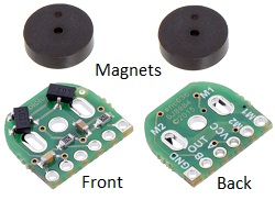
- There are two main types of encoders that can be fitted to gearmotor extended back shafts – optical and magnetic, The optical encoders produce a low level signal that needs extra processing before it can be reliably used, so UKMARSBOT has been designed to enable the use of magnetic encoders which produce a clean 5 volt digital signal out of them. Pimoroni and Polulo sell these at under £10 for a pair of them. Note that the latest versions of these have slightly larger holes in them for the motor power connectors which makes fitting them a bit easier
Fitting the Encoders
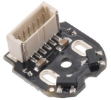
- Fitting the magnetic encoders to the motors is a fiddly job. The board has to have the extended back shaft going through the middle hole, and the 2 motor power connections are soldered into the other 2 holes in the encoder board. When you solder the power connections to the encoder board you must keep the back shaft centred in the middle hole so that it does not rub on the encoder board. It also needs six wires going from the edge of the encoder board to the motor connector on the robot main PCB. These wires can be soldered on or you can get a version of the board with an in place 2mm spacing edge connector. See the Polulo page at https://www.pololu.com/product/3081
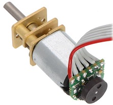
- If you are soldering wires to the encoder board you can connect the wires to the board and then the board to the motor or the other way round. The board fits over the extended back shaft and needs to be fitted so that the 2 black hall effect chips on the front of the board are away from the body of the motor and adjacent to where the round magnets will be placed. If you connect the wires to the board before fitting it to the motor make certain that the wires come out of the back of the board as shown on the picture. We suggest using Dupont connector jumper wires to plug into the pin or sockets that you have used for the motor connectors.
- A detailed video of one approach to fitting the encoders is available on you tube
- Once you have the board fitted to the motor you can push the magnet onto the shaft so that it is just clear of the hall effect chips. If your motors are mounted for inboard wheels you should have a few millimetres between the ends of the two extended back shafts. To reduce interference between the two magnets a small steel washer can be put on the outside of the magnet, furthest away from the motor body.
- The six wires from the encoder match the 6 connectors on the main PCB for each motor in the same sequence M1, M2, VCC(5v), Encoder output A, Encoder output B, Ground. If your encoders say 3.3v on them do not worry as they will also run from the 5 volts supply on the motor connectors. in fact they should work with anything from 2.8 to 28 volts.