Wall Sensor Basic Printed Circuit Board (PCB)
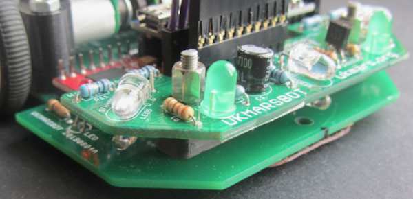
The basic wall sensor circuit board for the robot implements a series of circuits that connect the various electronic parts together. these circuits are very similar to the ones for the line sensor but there are only 3 photo transistors, and the LEDs and phototransistors are positioned to reflect light from the walls rather than the ground. These circuits and their functions are described below:
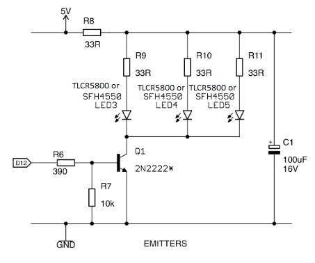
Emitters
This circuit uses the D12 trigger signal from the Nano to switch on a transistor. This then supplies current through the limiting resistors to the LEDs that illuminate the wall that is being followed.
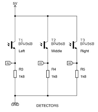
Detectors
This circuit shows the three phototransistors that are used to measure the light returning from the illuminated walls. Series resistors are used to limit the current flowing through the phototransistors which also affects the sensitivity of the detectors. Analogue values from the detectors are fed back to analogue inputs A0, A1, and A2 on the Arduino Nano.
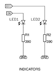
 Indicators
This circuit takes Nano digital outputs D6 and D11 and feeds them to 2 LEDs used as indicators. These could be used for instance to indicate whether particular detectors are seeing a wall or not.
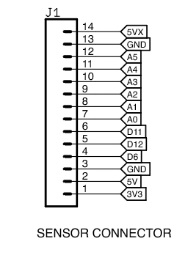
Connector
This part of the circuit shows the connector that is used to pass the signals to and from the main board. It is designed so that it will line up with the connector on the main board.