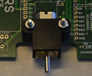
- For wheels of up to 32mm diameter the motors are mounted so that the wheel on the motor’s D shaft fits into the cut out at the side of the main board. Two screws are inserted in the holes from the bottom of the board to connect with the nuts in the motor mounting brackets. Depending on the source of the brackets these may use M2, M2,5 or M3 screws. If your bracket uses M3 screws you will need to slightly enlarge the holes in the main PCB to make them fit. The motor bracket goes over the gearbox part of the motor as shown here.

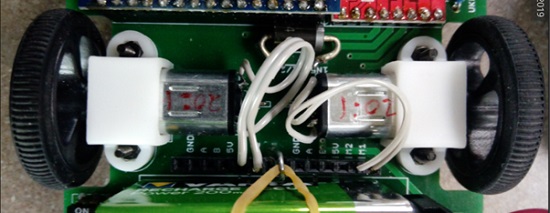
- If using motors with extended shafts, there should still be a few millimetres between the extended shafts of the 2 motors. This allows enough space for magnetic encoders to be fitted to the shafts.

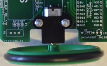
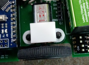
Note: When removing the wheels from the shafts DO NOT just try to pull them off as you may pull the gearbox off from the motor. Use a small screwdriver inserted between the gearbox and the wheel hub, and lever the wheel off the shaft this way. - If using larger wheels than 32mm, you will need to use the extended motor brackets which will be fitted over the gearbox part of the motor as shown. This will bring the motor D shafts further out so that the wheels extend beyond the edge of the main PCB.