
This page describes the 2 versions of the Half Size Line sensor board and the 19mm wide line one
The 2021 Half Size Line Sensor board assembly
These are the instructions for the UKMARS half size line follower board marked UKMARSBOT 2021- Nov -15
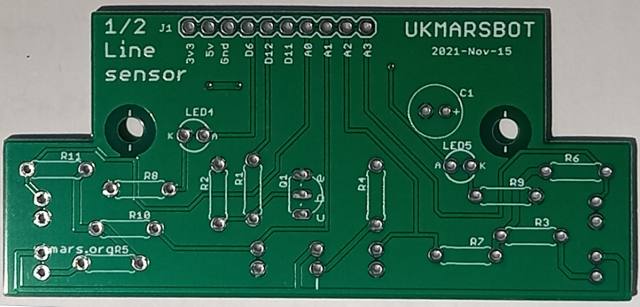
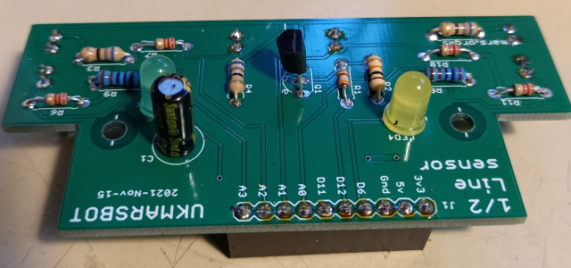
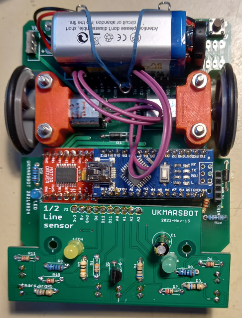
The components are almost the same as for the full size line follower but we have excluded a couple of items to simplify things and save space on the board. The board is designed to plug directly onto the UKMARS main board. This is the top of the half size line sensor circuit board:
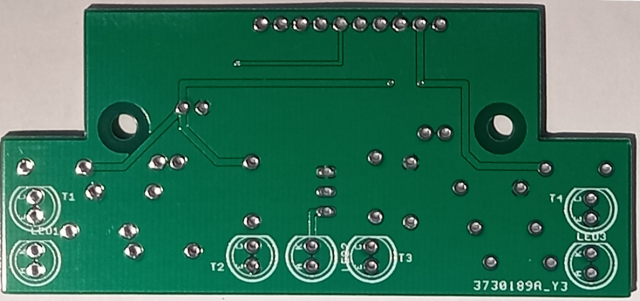
and here is the bottom of the board::
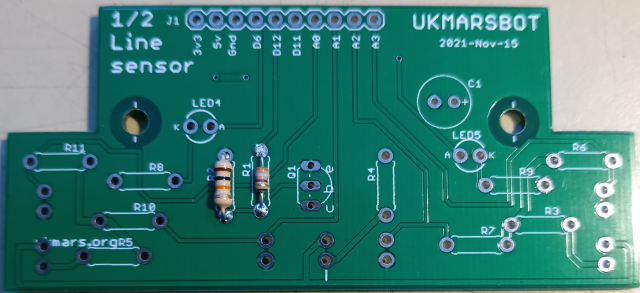
Start by adding resistors R1 390 ohms and R2 10K ohms to the top of the board these provide the bias for the base of transistor that switches the LEDs on and off
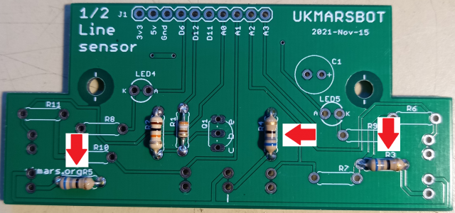
Next add resistors R3, R4 and R5 – all 68 ohms. These are the 3 current limit resistors for the 3 LEDs
Now add resistors R6, R7, R10 and R11 – all 2.2K ohms. These are the load resistors for the 4 phototransistors
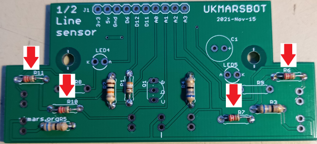
Now add R8 and R9 – both 1K ohms. These are the current limiting resistors for the 2 indicator LEDs

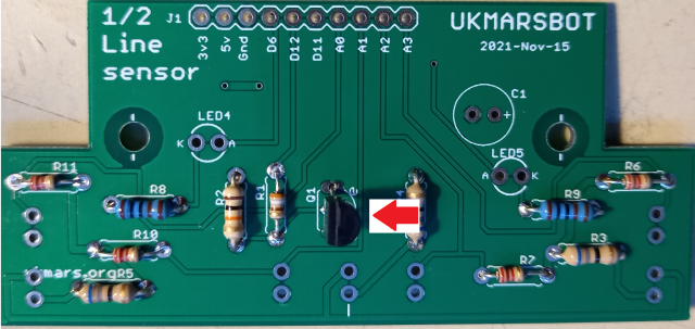
Now put in the LED switching transistor Q1 ensuring that it has the flat side to the left as shown.
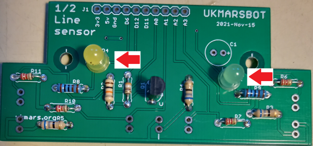
Next add the 2 indicator LEDs, LED4 and LED5. They can be any colour but it is best to have 2 of different colours, Almost any LED will work and they can be either 3 or 5mm. I have used one yellow and one green 5mm one here. Ensure that the long lead of the LED (the positive lead) goes into the side of the hole marked A (for anode). Note that LED4 has the +ve lead to the right and LED5 has the +ve lead to the left
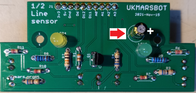
The final item on this side of the board is the 100 microfarad capacitor C1. It stands upright and is polarised so must be put in the right way round with the positive lead going in next to the + sign.. The side of the capacitor will normally have a lighter band with one or more minus signs on one side, so the other side is the positive lead.
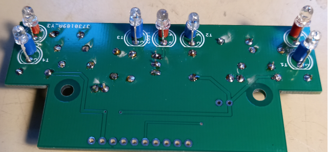
Now turn the board over and put in the three high brightness Truopto OSHR3131A-NO LEDs, LED1, LED2 and LED3. A small red spacer of about 5mm on the long lead is useful to help make the LEDs stand off a bit from the board and helps to make sure you put them in the right way round with the long red lead adjacent to the edge of the board in the A (for Anode) hole. You can make the spacer from a short piece of insulation stripped from a red piece of wire.
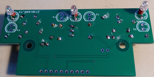
Now put in the four BPW85 phototransistors T1, T2, T3 and T4 next to the LEDs. Note that on this device the long lead is the emitter which is the negative lead. A small blue 5mm spacer on the long lead will help to ensure that you put these in the right way round with the long blue spacer lead in the E (for emitter) hole as shown here. Note that if you use a different phototransistor the emitter, and collector lead positions may be the other way round. Check the device datasheet and insert the Emitter lead in the hole marked E, and the Collector lead in the hole marked C.
Finally add the 10 way socket to the underside of the board, making sure that it is seated well down onto the board. Solder one end then the other end then check the seating before soldering the rest of the contacts.
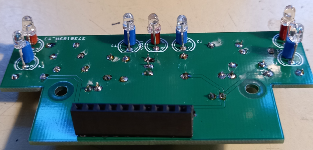
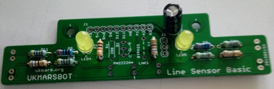
Turn over the completed board. It is ready to plug in and should look like this:
Before you plug it in you should set up the input and output pins on the Arduino Nano as specified in the Developer Notes Pin Assignments page
The board should be plugged into the 10 pins of J1 on the main board closest to the motor driver board
When seen from below, the phototransistors and LEDs should just be visible beyond the front of the board
A 3mm bolt can be inserted through each of the 2 holes at the front of the main board and then through a 12mm spacer and then through the 2 holes in the line sensor board. A nut on the top of each bolt will hold everything securely in place. If you only have a shorter spacer you can add a nut or two below it to make up the correct distance as shown here:
Your sensor board is ready to test – please remember that the trigger on pin 12 needs to be set high to switch on the LEDs and that about 100 microseconds delay should be given after switching on the LEDs for them to get to full brightness before reading the input from the phototransistors. After taking the readings you can switch off the LEDs again to reduce the battery load
Using the half width line sensor with a 3.3 volt CPU
If you are using this sensor with a 3.3 volts CPU board. e.g. with a Cytron Maker Nano RP2040 or a Raspberry Pi Pico or an Arduino Nano 2040 it helps to adjust the values of many of the resistors; The following resisters should be changed:
R3, R4 and R5 Replace the 68 ohms resistors with 33 ohm ones. This will gives 32 mA through the line illumination LEDs which should be plenty. If you want them even brighter use 27 ohm ones to get about 48mA through the LEDs.
R6, R7, R10 and R11 do not need changing from their existing 2.2Kohm values
R8, R9 Replace the 1K ohms resistors by 270 ohm ones. This will give about 6mA through the indicator LEDs
R1 and R2 do not need changing from their 390 ohm and 10K ohm existing values
Note that if using any of these boards you will need to disconnect or disable the 5v output from the CPU board and then connect the 3.3v and 5v lines together to feed the 3.3 volts into all of the robot circuitry. This is so that 5 volts is not fed back into any of the inputs on the CPU board as they are not able to handle inputs over 3.3 volts. Th simplest way to do this is to clip off the 5 volt pin from the CPU board so that it does not go into the CPU board socket.
The 2022 Half Size Line Sensor board assembly
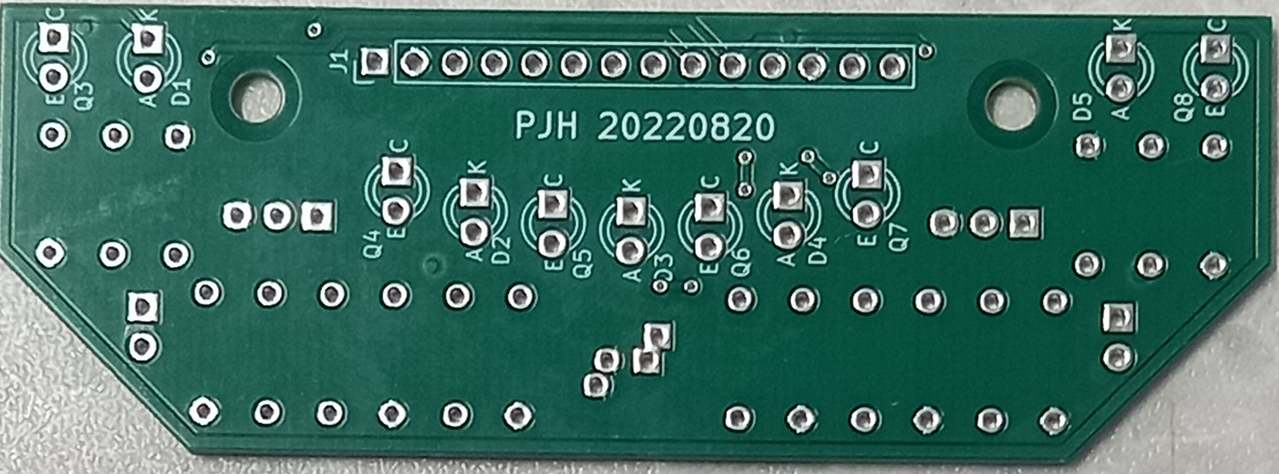
These are the instructions for the UKMARS half size line follower board marked on the front as LINE SENSOR MINI V1.0 and on the back as PJH 20220820. It is only intended for use with the v1.3 main board as the sensors are positioned to shine through the extra holes in the v1.3 board. The purpose of these changes is to move the side sensors backwards towards the wheels to make it better able to detect side markers on tight turns. It also has extra LEDs and sensors in an arc across the line.
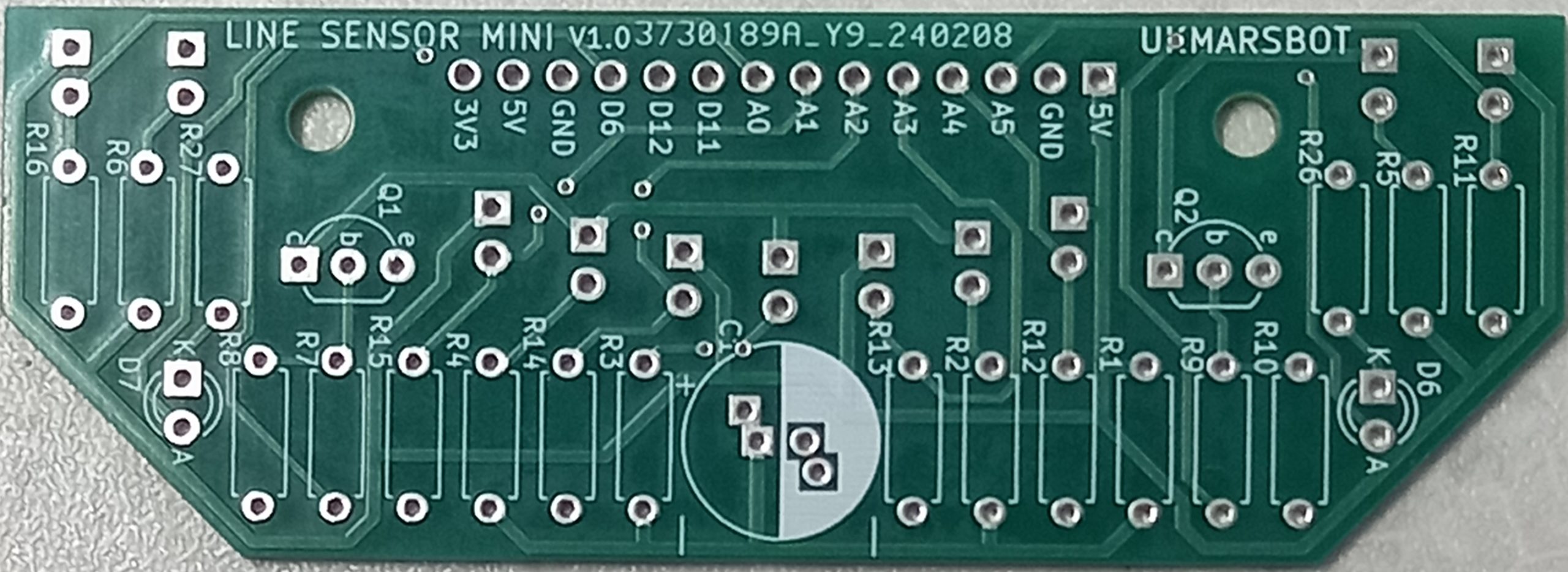
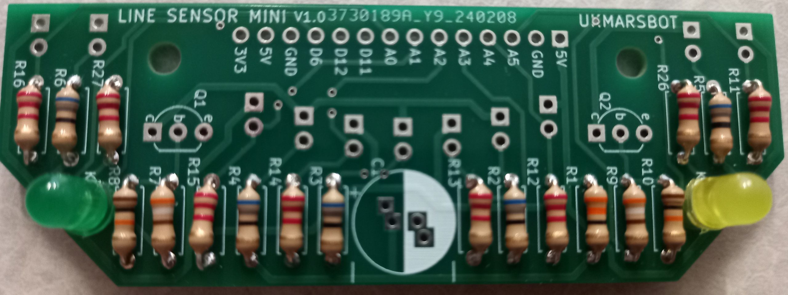
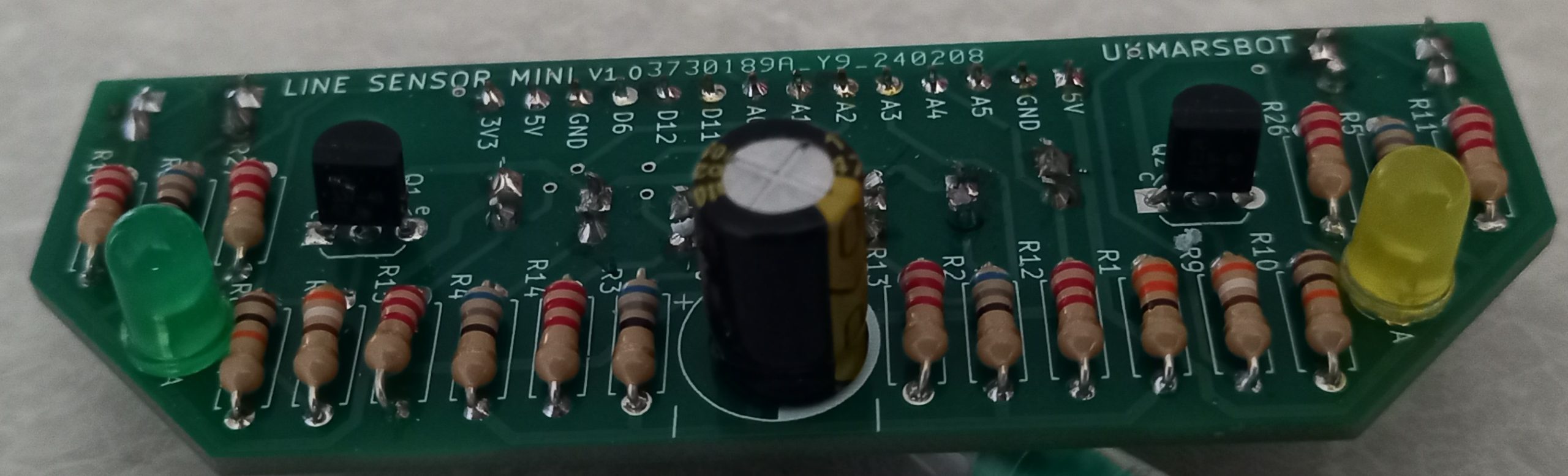
This is the top of the 2022 half size line sensor circuit board:
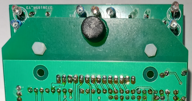
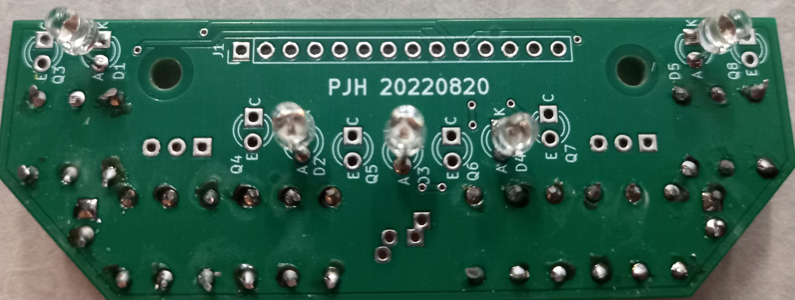
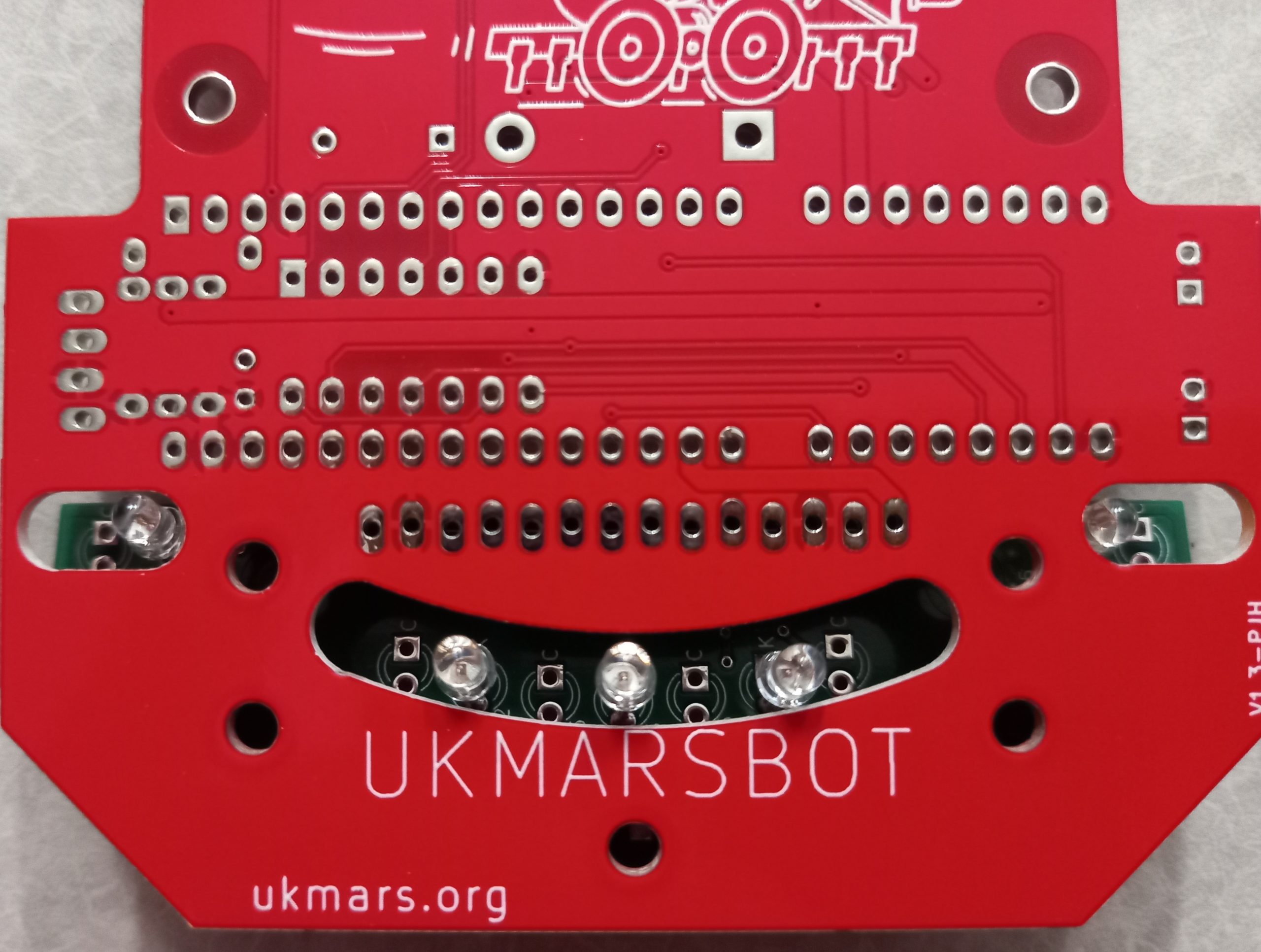
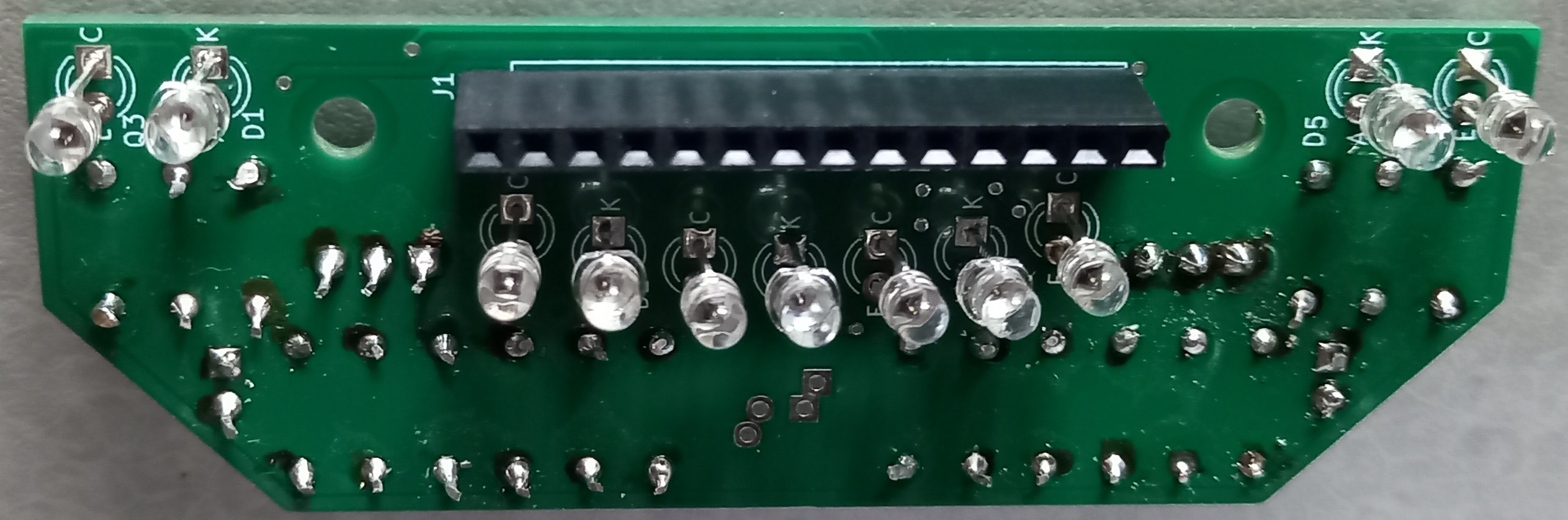
And this the bottom of the 2022 half size line sensor circuit board:
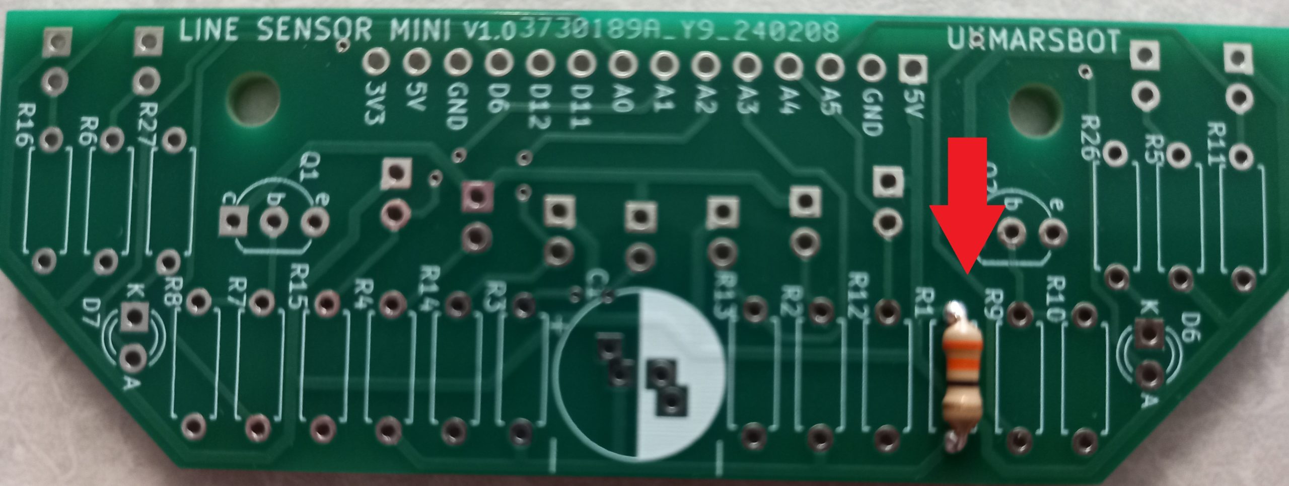
Start by soldering in all the resistors, which are placed on the top of the board
R1 = 33 ohms.
R2, R3, R4, R5 and R6 are all series limiting resistors for the 5 line sensor illumination LEDs and are all 68 ohms
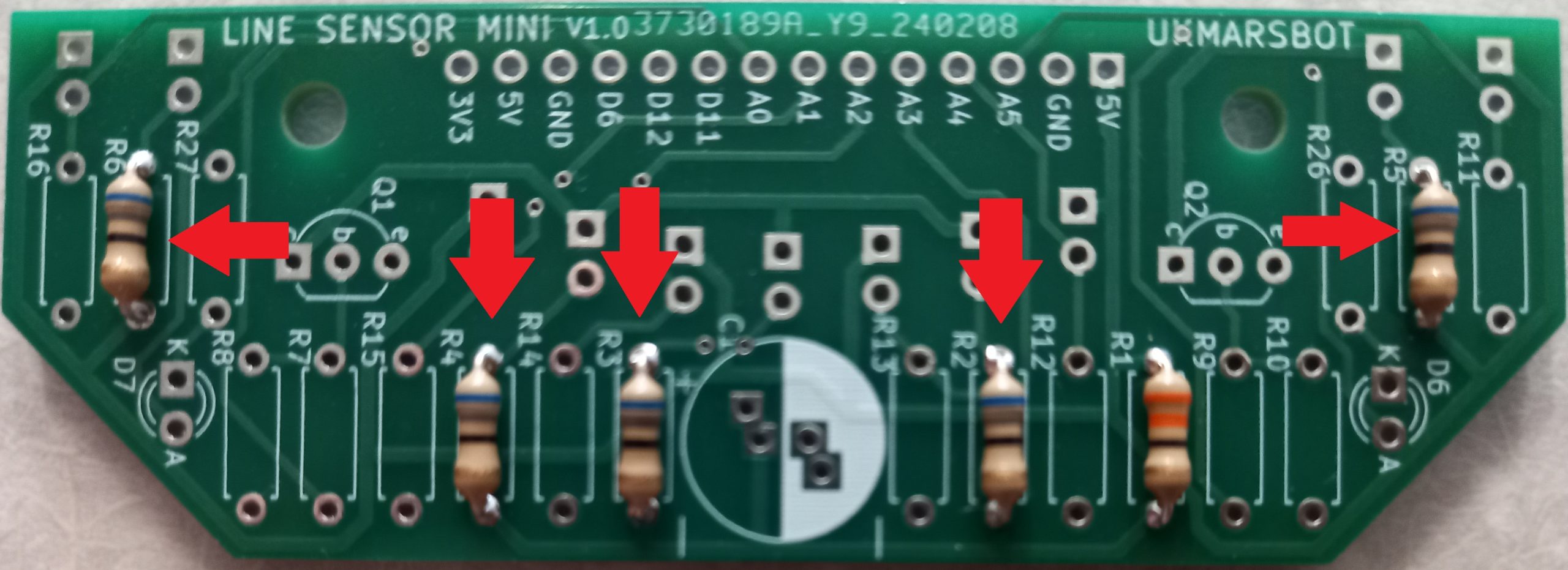
R7 and R9 are 390 ohms,
R8 and R10 which are both 10K ohms, provide the bias for the transistors that switch on the LEDs
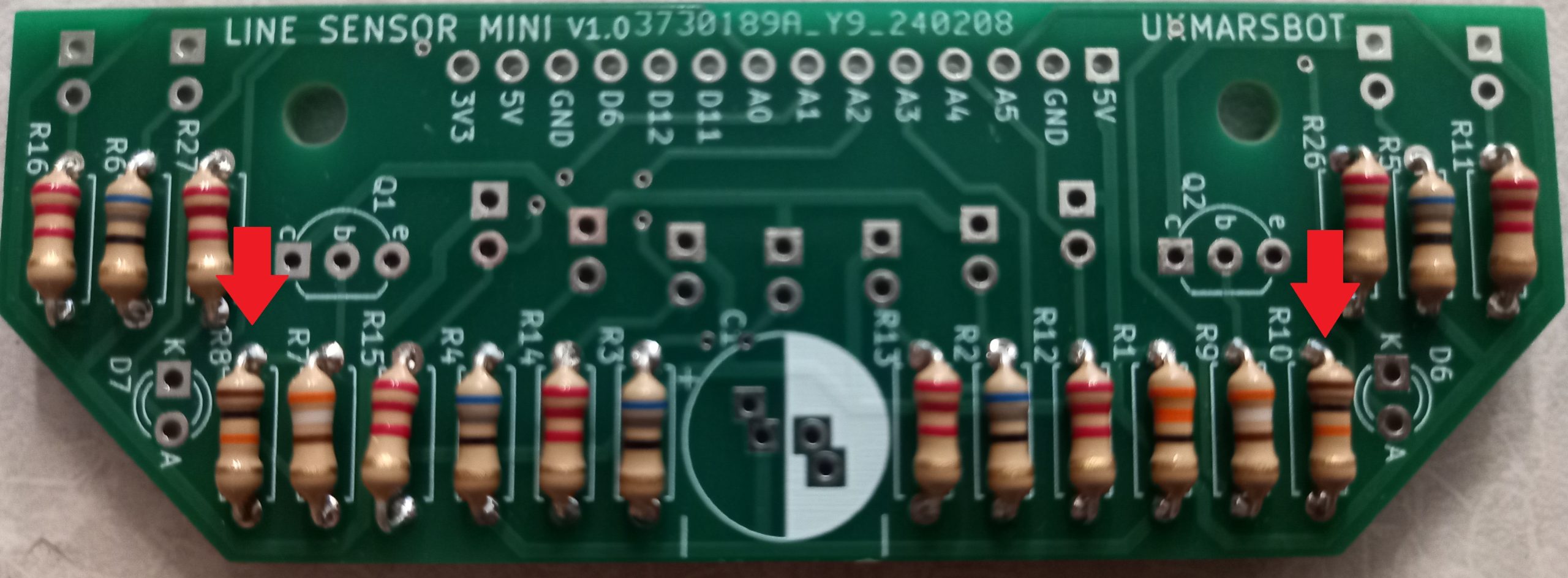
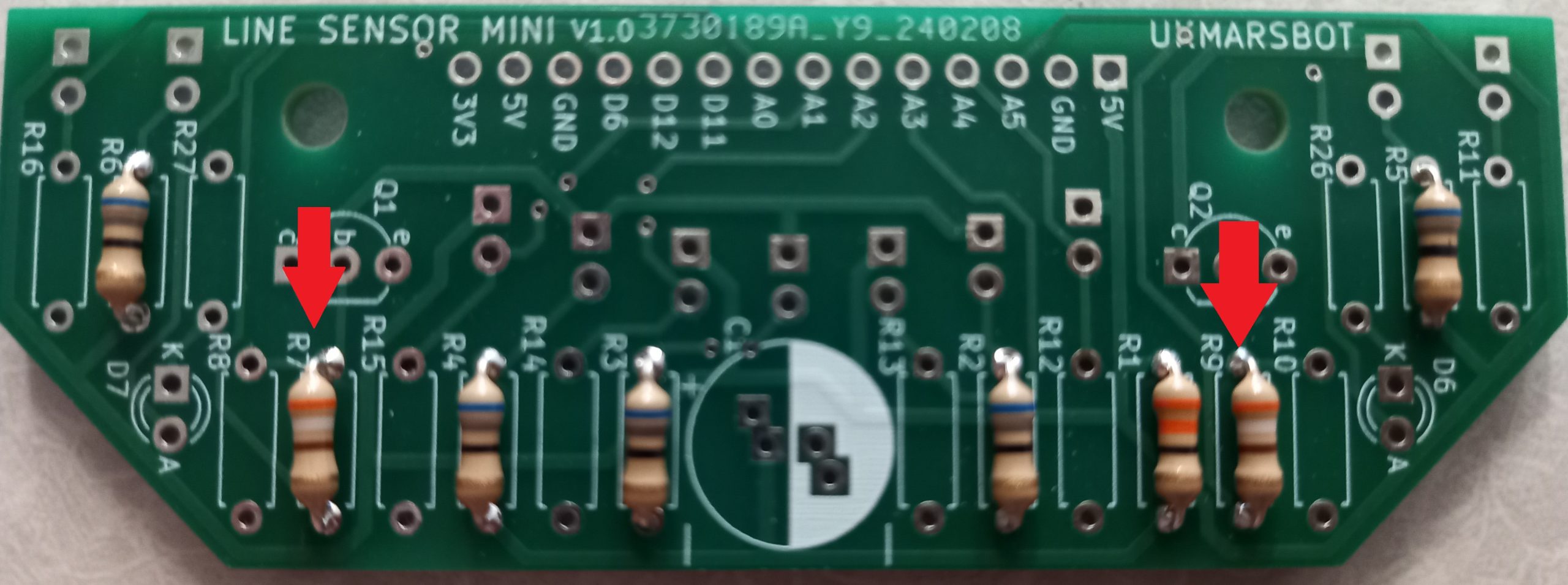
R11, R12, R13, R14, R15 and R16 are all 2K ohms and limit the current through the phototransistors
R26 and R27 are both 2K ohms and limit the current through the indicator LEDs. All the resistors should be populated now.
Next solder in the 5 LEDs marked D1, D2, D3, D4 and D5. These all go on the bottom of the board pointing downwards and so are soldered on the top. Make sure that they are inserted the right way round. The Anode which is usually the longer lead of the two goes in the hole marked A, and the shorter cathode lead goes in the hole marked K.
To get them all at the same height put a strip of card between the legs of the LED while you solder it in
It should end up like this
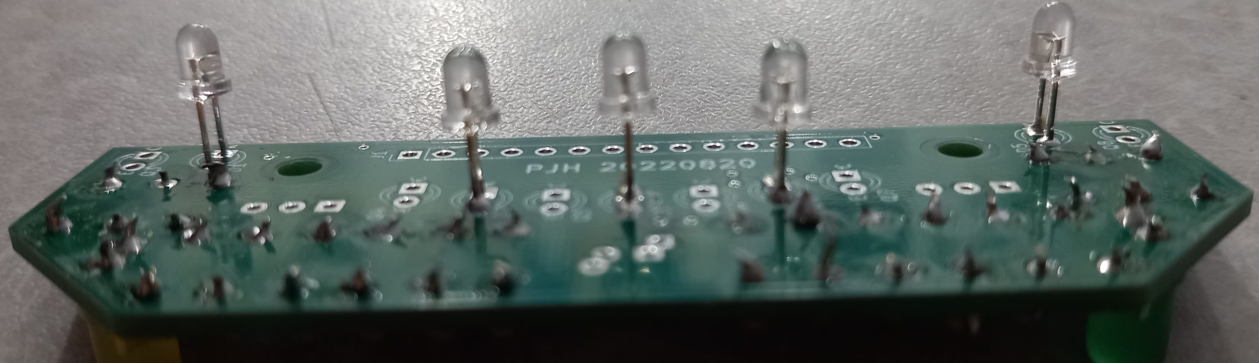
Check that they line up with the slots in the main board, and adjust if needed
Then solder in LEDs marked D6 and D7 which are the two indicator LEDs on the top of the board. It is helpful to use two different coloured LEDs such as a red and a green one but do not use blue or white ones as these require a higher voltage
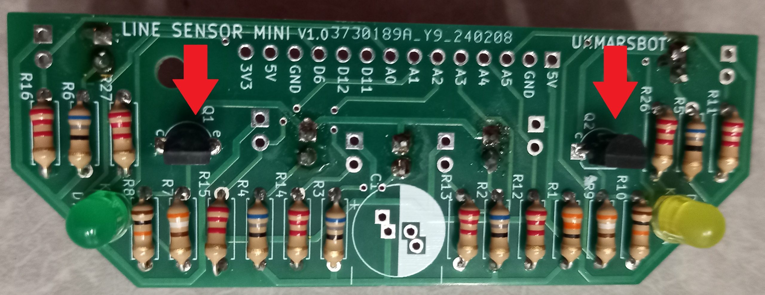
Next solder in the transistors Q1 and Q2 on the top of the board. These BC337 or equivalent transistors are used to switch on the centre or side illumination LEDS. Make sure that the flat side of the transistor matches the layout as marked on the board
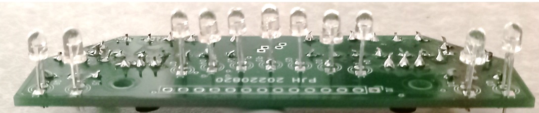
Next solder in the 6 phototransistors marked Q3, Q4, Q5, Q6, Q7 and Q8 that go on the bottom of the board facing downwards. Q1 to Q4 go in the centre and Q5 and Q^ are at the edges of the board. These BPW85C phototransistors go in the holes marked E (emitter) and C (collector) on the board. If using the BPW85C phototransistor the emitter is the long lead of the two. If using any other device check with the device specifications on the datasheet as to which lead is the emitter and which is the collector as they vary a lot between different devices.
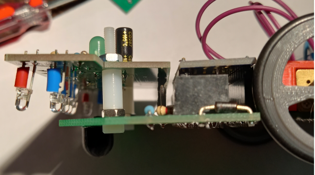
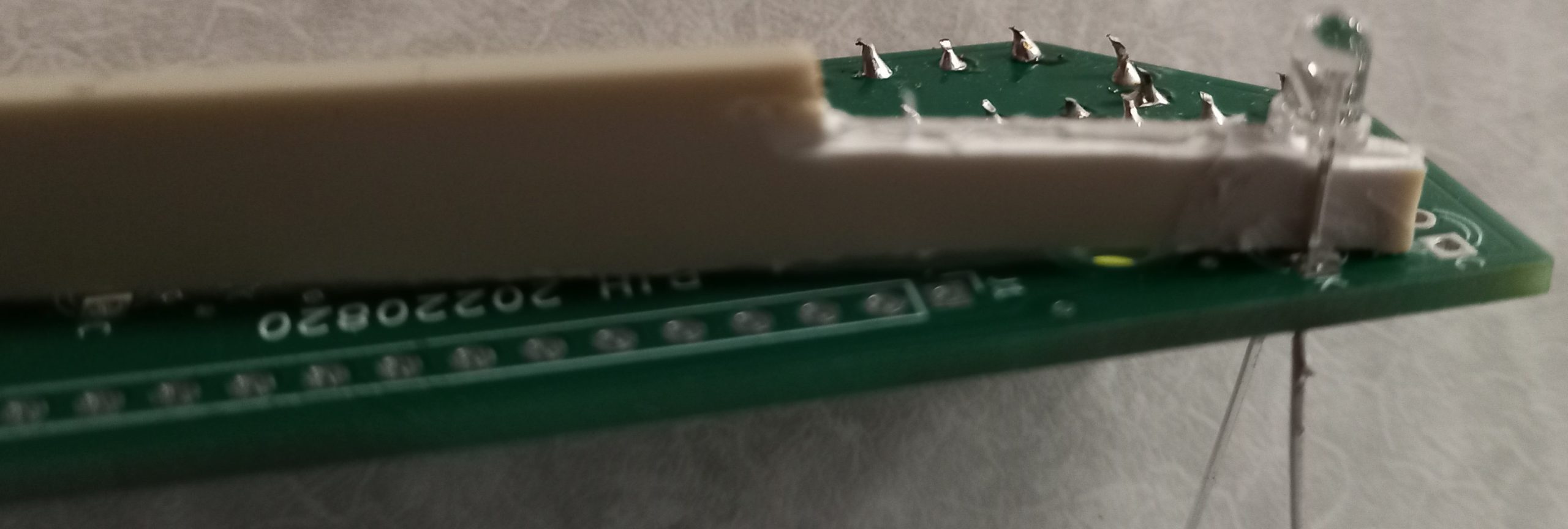
Looking from the side you should see them at roughly the same height like this:
If you have access to a 3D printer you can print a shroud that fits around the sensors but this is not essential. The STL file is available on our github pages at https://github.com/ukmars/ukmarsbot/blob/master/mechanical/sensor-guard-mini-wide.stl
Next insert the 14 way header on the bottom of the board, soldered on the top. This will connect the sensor board to the main board.
Finally add the capacitor C1 to the top of the board. It should be 470uF. This smooths the supply line to the sensors when the LEDs switch on and take current.. This is electrolytic so must go the right way round. Two sets of holes are provided to cope with different spacings on versions of this component. Choose the pair that allows the device to sit snugly down on the board. The negative side usually has a stripe or minus on it. Align this with the white section on the board.
Your board is now ready to test. Hold it in place with two 3mm bolts though the mounting holes in the sensor board and the main board. The phototransistors and LEDs on the underside should poke through the cut outs on the main board. Remember that you need to switch on the LEDs by putting a voltage on pin D12
Using the mini V1.0 line sensor with a python RP2040 CPU
If you want to use this line sensor board with a python based CPU such as the RP2040 which only has 4 A to D inputs there is a reduced build which just uses 4 rather than 6 sensors. Follow the link shown below for the build instructions for this build. RP2040 mini sensor build link/
The 19mm wide Line Following Sensor Board assembly
This sensor was designed for the original line following course which had a 19mm wide white line. The current UKMARS competitions now use a half size white line of approximately10mm with tighter turns.
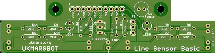
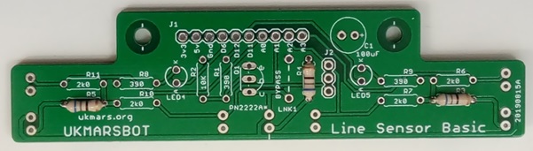
This is the full size line sensor circuit board top:
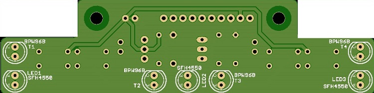
and bottom:
BUILD SEQUENCE
- Solder in emitter load resistors R3, R4, and R5 – all 68 Ὠ

Then the detector load resistors R6, R7. R10 and R11.The value of these detector load resistors depends on the photo transistors being used as detectors. If using the BPW85C phototransistor then use four 4.7K Ὠ resistors for R6, R7, R10 and R11 - If emitters are to be pulsed solder in resistors R1 390 Ὠ and R2 10K Ὠ that provide the biasing for the pulse transistor. If the emitters are to be left on all the time, omit these two resistors but put in a wire link on the PCB where it says LNK1 BYPASS
- If you want to use the two indicator LEDs, solder in resistors R8 and R9. Before you confirm these values and solder them in, check that the resistance is suitable for the LEDs that you use for LED4 and LED5. Do this by putting one resistor in series with an LED with 5V across it to check that it lights up. If using a high efficiency LED you may be able to use a larger resister of up to 1KὨ
- Solder in Capacitor C1 100µF making sure that it is oriented correctly. The longer lead should be the positive side and the negative side should be marked on the body of the capacitor. The PCB shows a + next to the positive lead.
- Solder in the two indicator LEDs LED4 and LED5. Make sure these are correctly oriented. The long lead on the LED should go to the hole marked A (Anode) and the shorter lead (and the side with the flat on the LED) should go to the hole marked K (cathode). Make the LEDs stand a few mm above the board by slipping a thin piece of paper between the legs of the LED between the LED and the PCB.

- If emitters are to be pulsed, add in transistor Q1. Correct orientation is essential. The transistor has a flat side which should be placed where the word Q1 is printed on the PCB. This will ensue that the emitter, base and collector go correctly into the 3 holes marked e, b and c
- Next we need to add the sensor LEDs and phototransistors. These are all mounted on the other side of the PCB to the other components. There are 3 LEDs and 4 phototransistors.
The values of these parts depend on whether you are using Infra-red invisible light or visible light. See Tools and Materials page for further details.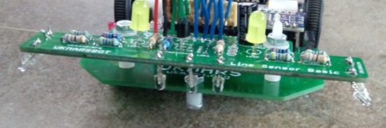
The 3 LEDs are soldered in with their long leads (+ve) towards the front of the board marked A. Leave sufficient length on the leads so that the ones at the sides of the board can be bent out by 30 degrees to see the side markers. Once they are soldered in, put 5v and Gnd on the relevant connector pins and 5v on D12 to check that they all light up.
Next put in the 4 phototransistors. If using the BPW85C these also go with their long leads towards the front of the board marked E (emitter). If using another phototransistor check from the datasheet which lead is the emitter and orient them accordingly. Make sure that there is enough length on the side ones to bend them out by 30 degrees to match the LEDs.
- Ten of the 11 holes of connector J1 on the sensor board now need to be attached to a 10 core multi-way wire or by 10 connector leads to the sensor socket on the main board. You do not use the 3.3v connection at the end marked J1. These will plug in via whatever connectors you use into the group of 10 adjacent pins marked from 5v through to A3 on the main PCB. The easiest solution is to use 5 Female to Female Dupont connector leads cut in half with the cut end soldered into the sensor board so that the 10 female ends plug into the Pin header on the board.
- The sensor board is fixed to the main PCB with two M3 screws with a 10mm spacer between the main PCB and the sensor board, with the nuts on top. These M3 screws go through the front set of two holes in the main PCB from the bottom.