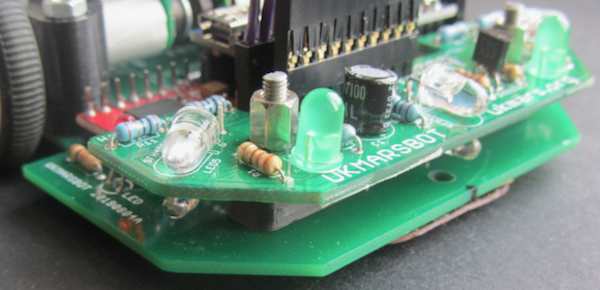
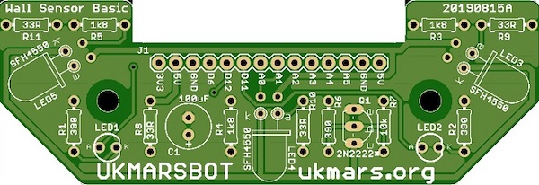
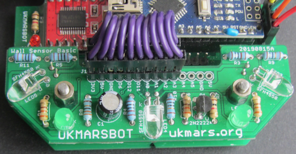
This is the wall sensor circuit board top:
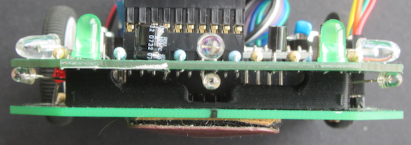
and bottom:
There are two options for this sensor: The first using infra red (IR) invisible light, and the second using visible light. Different LEDs and resistor values are used for the 2 options.
WARNING: If you look directly into any high power LED you could damage your eyesight. This is particularly true if you are using invisible infra-red light as the blink response of the eye is not triggered by infra-red. So if you have any concerns about this, or are building this wall sensor in an environment where you do not have full control of every item built (such as in school projects) you should go with option 2 and use the visible light LED. Even then, you should warn the builders not to look directly into the LEDs or point them at other persons.
BUILD SEQUENCE
Before completing steps 1-6, study this picture of an assembled board so that you can see the orientation of the parts: Note that the part values shown on the PCB are those for the IR version of the board.
- Solder in emitter charge resistor, R8 (33Ὠ) and the current limit resistors R9, R10, and R11 – (IR version all 33Ὠ, Visible light version 10Ὠ)
Then the detector load resistors R3, R4 and R5.The value of these detector load resistors depends on the photo transistors being used as detectors. If using the BPW96B phototransistor use these 3 resistors (IR version 1.8KὨ, visible light version 1KὨ.) - Solder in resistors R6 390 Ὠ and R7 10K Ὠ that provide the biasing for the emitter pulse transistor. (same for both versions).
- If you want to use the two indicator LEDs, solder in resistors R1 and R2 both 390 Ὠ. Before you confirm these values and solder them in, check that the resistance is suitable for the LEDs that you use for LED1 and LED2. Do this by putting one resistor in series with an LED with 5V across it to check that it lights up. If using a high efficiency LED you may be able to use a larger resister of up to 1KὨ
- Solder in Capacitor C1 100µF making sure that it is oriented correctly. The longer lead should be the positive side and the negative side should be marked on the body of the capacitor. The PCB shows a + next to the positive lead.
- Solder in the two indicator LEDs LED1 and LED2. Make sure these are correctly oriented. The long lead on the LED should go to the hole marked A (Anode) and the shorter lead (and the side with the flat on the LED) should go to the hole marked K (cathode). Make the LEDs stand a few mm above the board by slipping a thin piece of paper between the legs of the LED between the LED and the PCB.
- Add in emitter pulse transistor Q1. Correct orientation is essential. The transistor has a flat side which should be placed next to R6 on the PCB. This will ensue that the emitter, base and collector go correctly into the 3 holes marked e, b and c
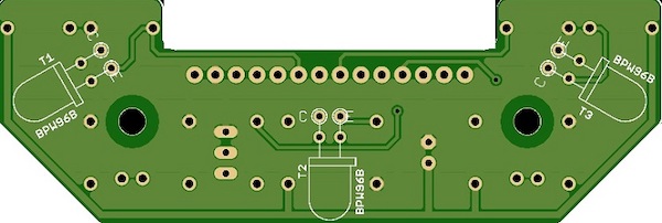
- Next we need to add the sensor LEDs and phototransistors. For the IR version the 3 LEDs are SFH4550. For the visible light version the 3 LEDS should be TLCR5800. The 3 phototransistors can be either BPW96B or BPW85C for both versions. The 3 LEDS (LED3, 4 and 5) are mounted on the top of the board whilst the phototransistors (T1, T2 and T3) are all mounted on the other side of the PCB to the other components.
The LEDs must be mounted before the phototransistors or you will not be able to access the pads. Take care to make the leads long enough so that the LED body will be flush with the edge of the board: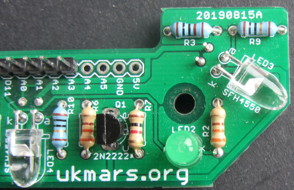

The 3 LEDs are soldered in with their long leads (+ve) towards the front of the board marked a. Once they are soldered in, put 5v and Gnd on the relevant connector pins and 5v on D12 to check that they all light up. - Next put in the 3 phototransistors on the bottom of the board but soldered on the top. If using the BPW96B these go with their long lead (the emitter) towards the back of the board marked E. If using another phototransistor check from the datasheet which lead is the emitter and orient them accordingly.
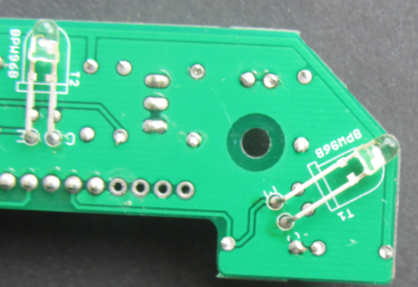

IMPORTANT: The leads on the phototransistors must be left long so that the device ends up flush with the edge of the PCB - Eight of the 14 holes of connector J1 on the sensor board now need to be attached to an 8 core multi-way wire or by 8 connector leads to the sensor socket on the main board. The pins are connected from the end marked J1 (5V to A2). These will plug in via whatever connectors you use into the corresponding group of 8 adjacent pins marked from 5V through to A2 on the main PCB. The easiest solution is to use Female to Female Dupont connector leads cut in half with the cut end soldered into the sensor board so that the 10 female ends plug into the Pin header on the board.
- The sensor board is fixed to the main PCB with two M3 screws with a 10mm spacer between the main PCB and the sensor board, with the nuts on top. These M3 screws go through the front set of two holes in the main PCB from the bottom.
Here are some views of an assembled board mounted to the robot. This one uses short DuPont leads and pin headers instead of soldering the wires to the board: