Below are the circuits relating to the main chassis PCB. These are followed by those for the Mezzanine board which holds the processor and connected to the sensor boards
Main Chassis PCB
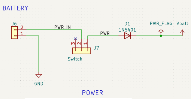
Firstly the battery and main power circuit that powers the motors. Note the protection diode to prevent the battery being connected the wrong way round
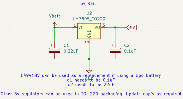
This provides the 5 volt supply for the processor and motor driver
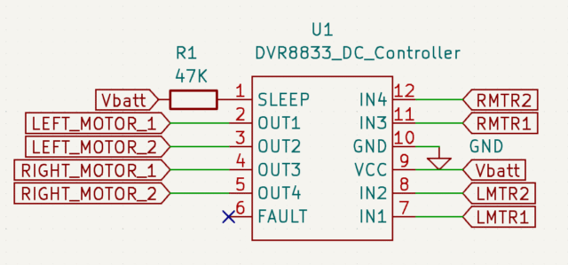
This is the motor controller circuit
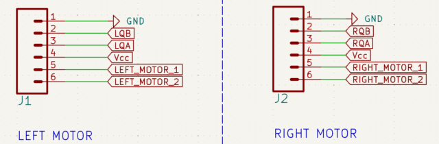
These are the left and right motor connections
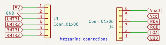
These are the connections to the mezzanine board through the two 6 pin connectors
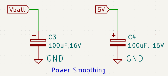
Finally the power smoothing circuits
Mezzanine PCB
Below are the circuits for the mezzanine board
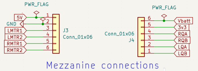
This connects the mezzanine board to the main chassis via two 6 pin connectors
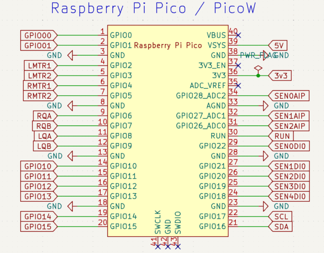
These are the processor Raspberry Pi Pico connections. They are the same for whichever version of the Pico you are using
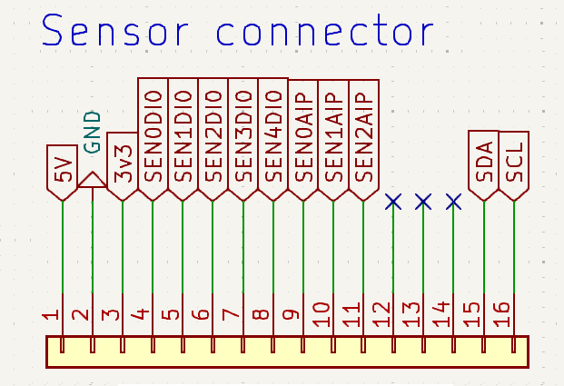
This is the 16 pin sensor connector J1
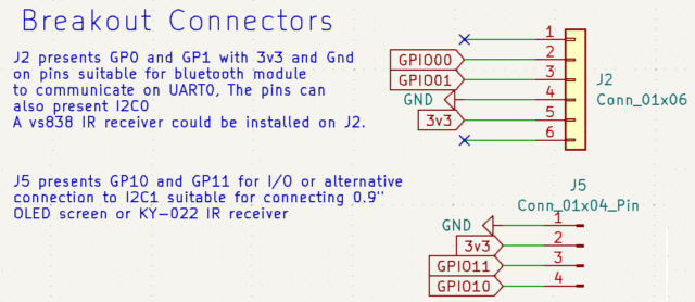
There are 2 breakout connectors J2 and J5 that can be used in several different ways as described
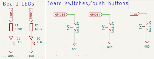
These 2 LED indicators can be used as you wish, such as for showing which program has been selected on the tactile switches. Also 2 of the 3 tactile switches SW1 and SW2 can be read by the Pico. The 3rd one SW3 is a reset button for the processor.