These are the circuits on the line sensor PCB
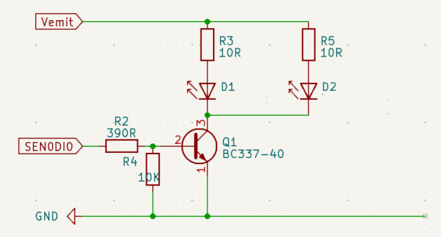
This circuit drives 2 of the 3 LEDs, the one at the front over the middle of the line and also the one on the right side that lights the start and end markers on the right side of the line follower track
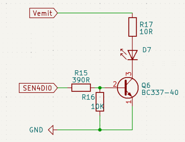
This circuit drives the other LED which lights the change of radius markers on the left side of the line follower track
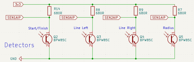
These are the 4 phototransistor detectors that measure the light coming back from the illuminated line. Note that the signals from the Start/Finish detector and that from the Radius detector on the other side both go the same analogue input on the Pico. This is because the Pico only has 3 analogue to Digital inputs so we have to multiplex two of the inputs together. By deciding which of the LEDs to light at what time we can differentiate the detection of the Star/Finish marker from that of the Radius marker.
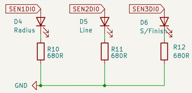
This is the circuit for the 3 indicator LEDs that you can use as you wish, such as showing if a marker has been detected
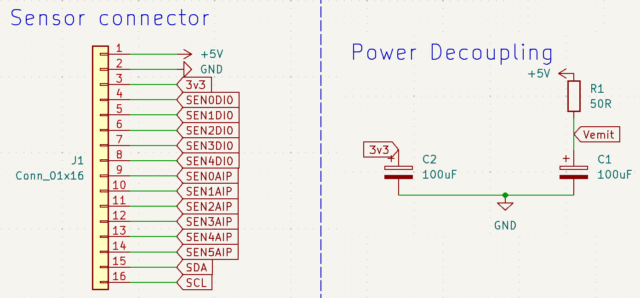
Finally, these are the connections from the mezzanine board to the line sensor board, and also the power decoupling and smoothing capacitors