
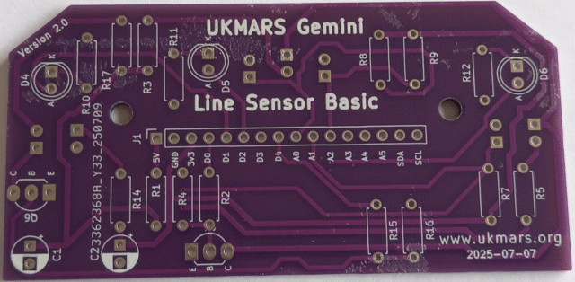
The Line Following Sensor Board
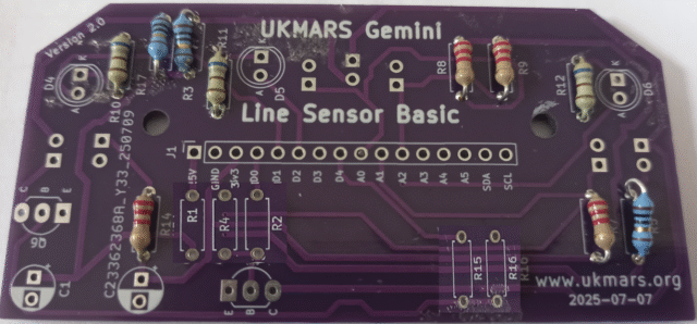
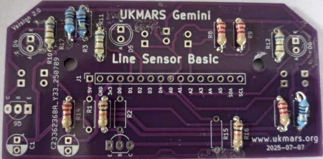
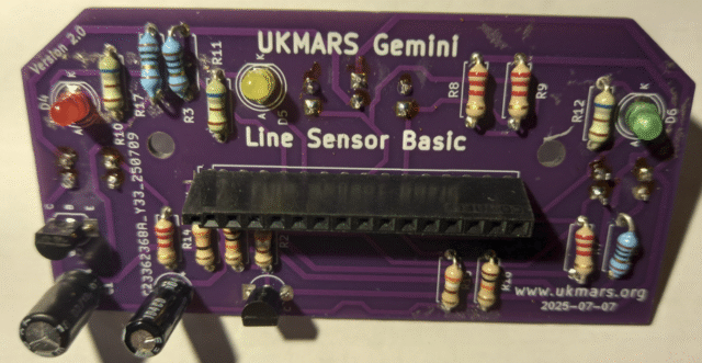
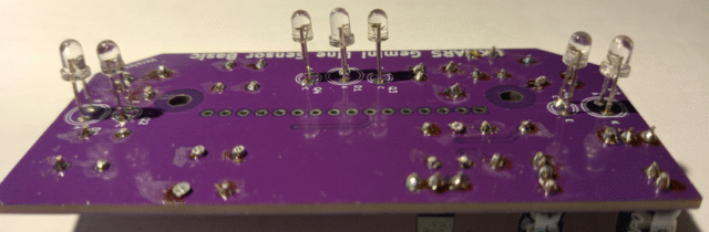
This is a view of the top of the PCB
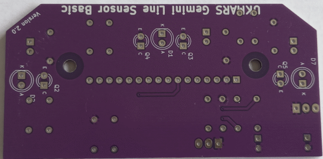
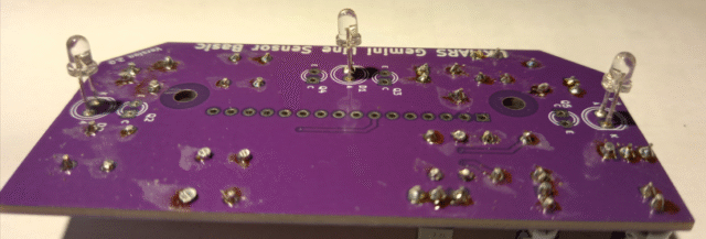
This is the bottom of the PCB
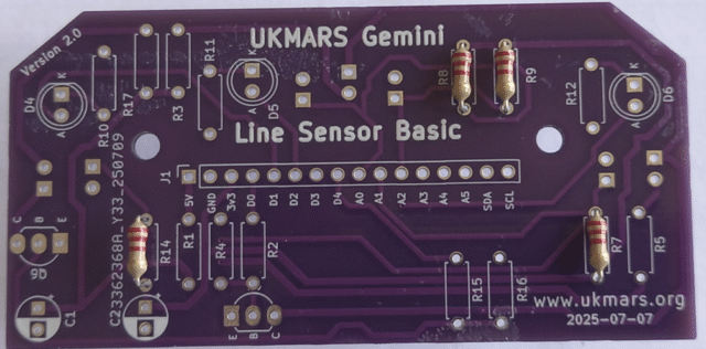
We start by adding the resistors. There are 15 of these of 6 different values so be careful which ones go where. Bend the leads over as close to the body of the resistors to get them to fit into the holes.
R7, R8, R9 and R14 are all 2.2k ohms (colour banded red, red, red) so put these in first
Then add R3, R5 and R17 which are all 10 ohms (colour banded brown, black, black) shown here with blue bodies.
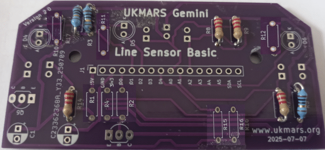
Then add R10, R11 and R12 which are all 680 ohms (colour banded green, grey, brown)
Then add R4 and R16 which are 10K ohms (colour banded brown, black, orange)
Then add R2 and R15 which are 390 ohms ( colour banded orange, white, brown) Do not get these mixed up with teh 39 ohm resistors which have just the final band different.
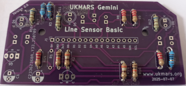
Then finally add R1 which is 33 ohms (colour banded orange, orange, black)
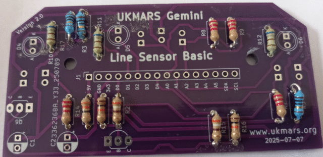
You should now have all 15 resistors in place. Check them before going further with the build.
New we will add the two BC337-40 transistors Q1 and Q6. Insert them so that the flat side matches the flat side shown on the screen print. Q1 has the flat side at the back, while Q6 has the flat side at the front.
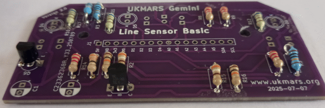
Now put in the 3 indicator LEDs D4, D5 and D6 put the longer lead at the hole marked A (for Anode) It is suggested that you use one red, one yellow and one green one to make it easiest to tell which is lit when it is moving. These are the low current LEDs just used as indicators. Do not put the high brightness RED LEDs in these positions
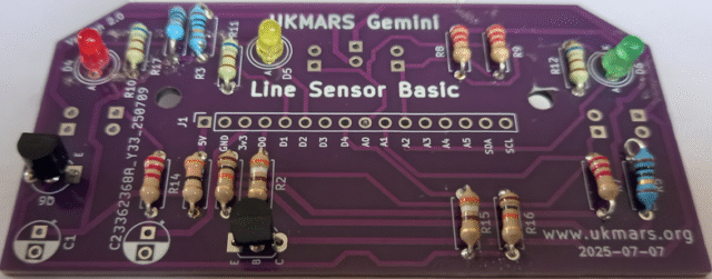
Next to go on the top of the board are the electrolytic capacitors C1 and C2. Ensure that they go in with the negative strip on the side of the capacitors at the back of the board where the white segment is shown on the screen print.
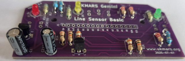
The last item to go on the top of the board is the 16 way female socket which will make the connection to the mezzanine board for all the circuits. Solder this in carefully on the bottom of the board, making sure that it is seated fully down on the board and upright.
The other parts go on the other side of the board and are soldered on the top. First put in the 3 line illumination LEDs One goes in the centre and one on each side. Make sure that the long lead goes on the hole marked A (for Anode). Note that on one side the Anode is towards the front and on the other side it is towards the back. The base of the LEDs need to stand proud of the board by about 5mm. To get this correct amount, spread the leads slightly before you put them in the holes then put them in until the slight notch on the leads touches the board. Now solder one lead then check both the distance from the board and that the LED is standing precisely upright. If needed, adjust the height or angle then solder the other lead.
Now put in the 4 phototransistors Q2, Q3, Q4 and Q5. Make sure that the long lead goes in the hole marked E (for Emitter). Set them at the same height off the board as the LEDs and use the same process as above to get the height and angle correct. Note that the emitter is towards the back of the back on Q5 while for all the other three the emitter is towards the front
Your line sensor board is now complete