
Once you have completed the PCBs that you want to use, and have the other parts as specified, we can start to assemble the robot.
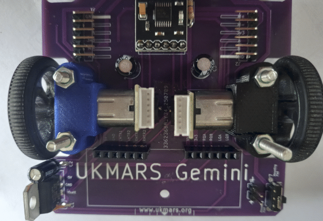
Step 1 – If you are using 3D printed motor mounts, attach the motors to the main chassis PCB using 2 M3 x 30mm bolts at the rear and 2 M3 x 20mm bolts at the rear. The bolts go from the bottom of the PCB through the motor mounts and are captured by M3 nuts. You can use metal or plastic bolts. The example below has motors with encoders fitted.
The STL file for the 3D printed motor mounts can be downloaded from Github at: https://github.com/ukmars/gemini/blob/main/mechanical/motor-bracket.stl Click on the down arrow on the top right side of the page to “Download the raw file” then “Save as ” an STL file on your computer
If you are using the Polulo bought motor mounts, these use thinner 2mm bolts but they attach in the same way. If you get some 30mm long 2mm bolts for the rear connections you can connect the rear 2 to the mezzanine board, but without these bolts going to the mezzanine board the 2 rear 6 pin connectors will hold the mezzanine board in place anyway.
If you are using motors with encoders, attach the leads between the encoder sockets and the 6 pin connectors above.
If you are not using encoders just connect the 2 motor power leads to the motor + and – connections on the J1 and J2 connecters as shown here. Use a female to female Dupont connector jumper cable cut in half with the cut end soldered to the motor power connections. Or you can even just solder the motor leads into the + and – connections of J1 and J2 but that will make it harder if you want to swap motors over later.
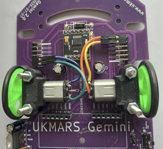
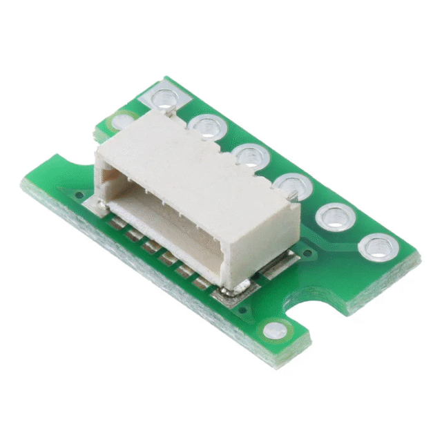
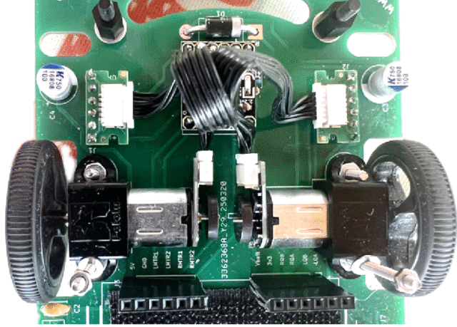
If you are using motors with encoders, connect the cable from the motor to the J1 and J2 connectors. Note that some motors have the encoder connector on the side and some on the top as per the image for the motor mounts above. If you are using a JST-SH, to JST-SH 6-pin 1.0mm pitch cable you will need an adapter board to convert the signals to 2.54 pitch to go into J1 and J2 instead of the angled pin connectors. Pi Hut do this side entry adaptor.
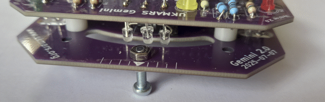
Adding the line sensor board
Using 2 M3 x 30mm plastic or metal bolts put the bolts through the rearmost of the 2 sets of holes next to the smiley cut out. Insert these from the bottom then put 2 x 10mm spacers on the bolts.
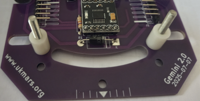
The line sensor board can now be dropped onto these bolts and an M3 nut put on each bolt to hold them down.
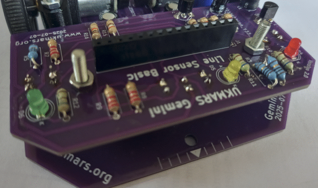
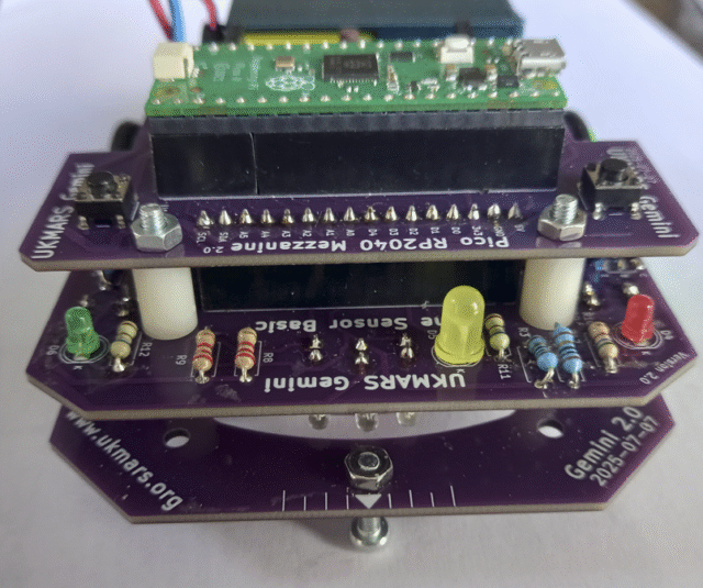
The mezzanine board can now be put in place with the 2 x 6 pin rear connectors at the rear and the line sensor connector connected to the bottom of the mezzanine board at the front. If your M3 bolts are shorter than 30mm long you can secure the sensor board to the main chassis with two M3 nuts as shown above. However if you have 30mm bolts, use two 10mm long spacers to link the sensor board to the mezzanine board and secure it with M3 nuts on top of the mezzanine board as shown below, after making sure that the mezzanine board is located correctly in the connectors at the front and at the back.
The battery goes at the back of the robot held in place by either some tape or Velcro. A PP3 format battery lead should either be directly soldered onto the battery connector pins or you can use a 2 pin socket to connect it to 2 battery contact pins located next to the on/off switch.
Your robot should now look something like this:
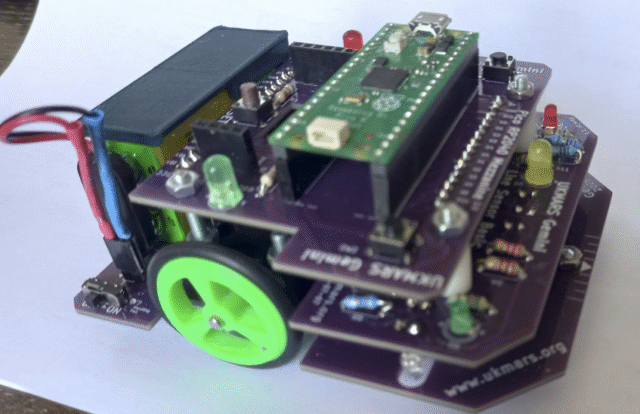
You now need some skids at the front and back to keep the robot level while travelling. A round headed m3 x12mm bolt with 2 nuts will provide a simple adjustable skid for the front as shown below. A simple pad of anything solid glued under the back of the robot will stop it tipping back as it accelerates but should not be touching the ground normally. A clearance of a couple of millimetres clearance is needed at the back to cope with any unevenness or bumps in the track. A couple of washers held on with some Blu-tack or hot glue will do nicely or you could 3D print some rounded skids for the front or back.
Your robot should be ready for testing now.