
The Wall Sensor Board is used for wall following and maze solving
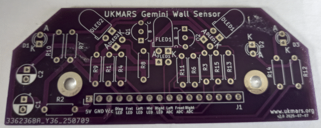
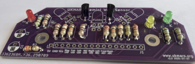
This is the view of the top of the PCB
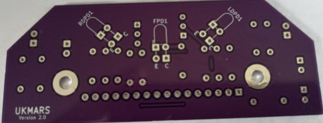
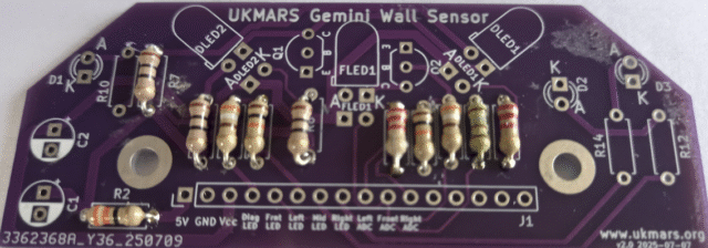
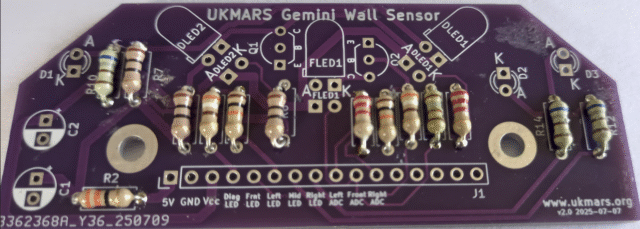
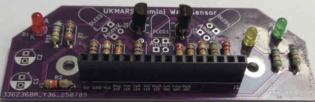
This the bottom of the PCB
We start by adding the resistors. There are 14 of these of 7 different values so be careful which ones go where. Bend the leads over as close to the body of the resistors to get them to fit into the holes.
First add the resistor R2, 33 ohms (colour banded orange, orange, black) which is used for power decoupling and then the R7, R8 and R9 resistors of 10 ohms (colour banded Brown, black, black) which are the three wall illumination LED load resistors
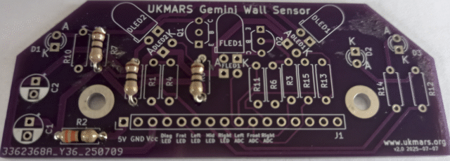
Next add R1 and R3 both 390 ohms (colour coded orange, white brown) used to current limit the current to the bases of the two transistors which switch the LEDs off and on
Then add R4 and R6 both 10K ohms (colour banded brown, black, orange) which provide the bias for the base of the transistors
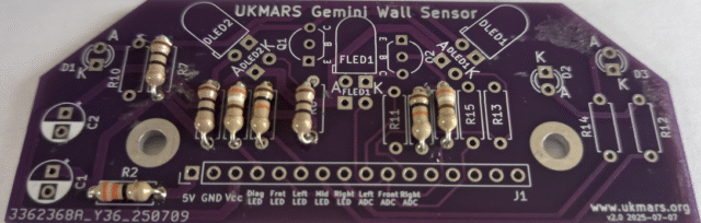
Now add the 3 phototransistor load resistors. R11 and R13 are 2.2K ohms (colour coded red, red, red) but R15 is 1.8k ohms (colour coded brown, green, red). This is to give the front sensor more range.
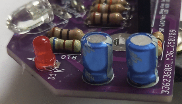
Finally go in the 3 indicator LED load resistors R10, R12 and R14, all at 680 ohms (colour coded green, grey, brown)
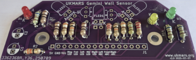
Next add the 3 low current indicator LEDs D1, D2 and D3. Make sure that the long lead goes into the hole marked A (for Anode) Note that not all of the LEDs are oriented in the same direction. Use 3 different colours for them e.g. red, yellow and green as shown here:
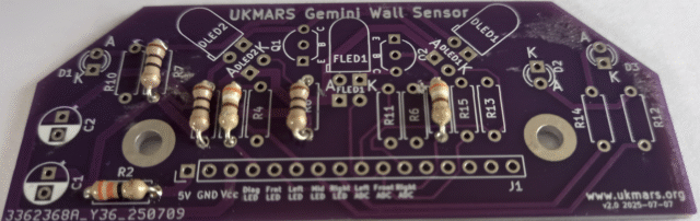
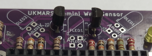
Now we will add the 2 transistors Q1 and Q2 marked BC337-40 Make sure that they go in with the flat side as shown towards the text FLED1 matching the layout shown on the board
Now we can add the 16 way female socket that connects to the mezzanine board. Solder in a pin at each end then check that it is seated fully down on the PCB and upright before soldering in the rest of the pins
Now we just have the wall illumination LEDs and phototransistors to go in. The three LEDs sit on the top of the board and are soldered beneath, but the phototransistors sit below the board and are soldered on the top. You must put the LEDs in first using the holes closest to the outline of the LED with the long lead going in the hole marked A (for Anode), as shown here.
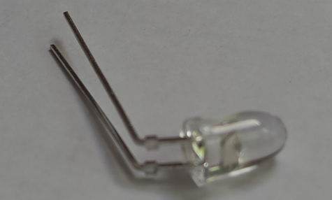
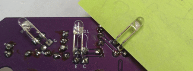
Bend the LEDs like this, making sure that the long lead is on the left ready to go in the A hole.
Once they are soldered in thy should look like this
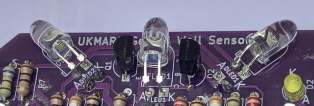
Now turn the board over and add the 3 BPW85C phototransistors RDPD1, FPD1 and LDPD1 putting the long lead in the hole marked E (for Emitter). Solder them on the top of the board just behind where the LED leads go through. The phototransistors should point in the same direction as the LEDs, one forward and two angled at about 45 degrees towards the side. Put a piece of paper beneath the leads while you solder them so that they do not short on the LED contacts below as
Then we will add the 2 100uF 16V electrolytic smoothing capacitors. They should be the 7mm high versions as specified in the parts list. They are polarised so make sure that the minus sign on the side goes to the back of the board on the white section of printing.
Your wall sensor board is now complete