
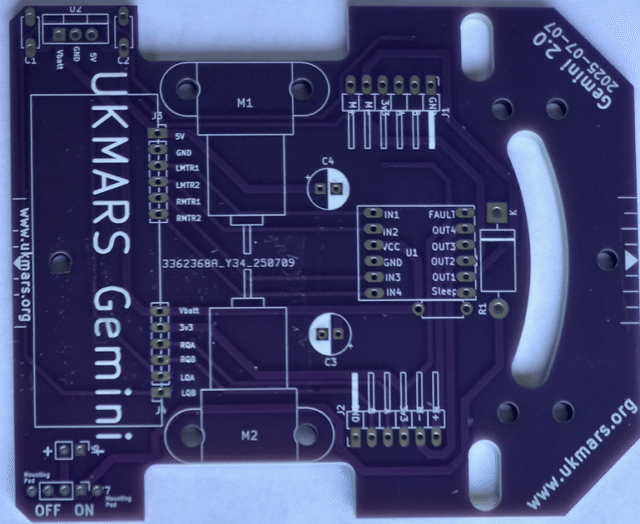
The Main Chassis Board
This is the main chassis top of the Gemini V2.0 board
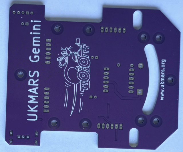
and this is the bottom of the Gemini V2.0 board:
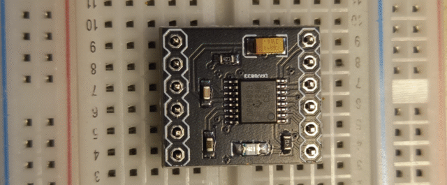
The build sequence is not critical. We will start with the DRV8833 motor controller board. If your DRV8833 board has not got headers soldered in already, put the headers into a breadboard to hold them upright Then put the board on top of them to enable you to solder the headers to the board. Yor 6 pin headers have a short and long lead. Put the long lead into the breadboard and solder the short leads onto the DRV8833 board.
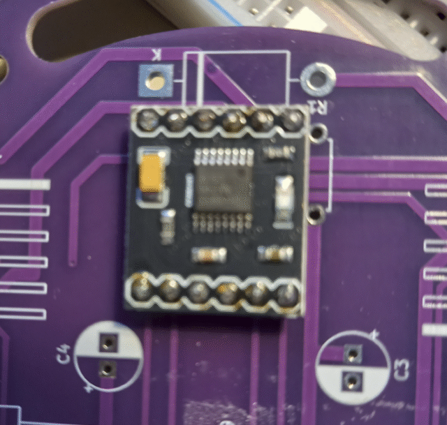
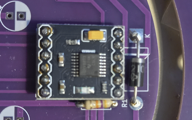
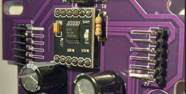
Now you can solder the DRV8833 board onto the main chassis board. Ensure that you put the board in the right way round as shown below with the large yellow capacitor on the left side. Then solder the 2 sets of 6 pins on the bottom of the board.
Next we will add the 47K ohm sleep wake resistor R1 and the polarity protection diode which are next to the DRV8833 board. The 47K ohm resistor (marked yellow purple orange) does not matter which way round it goes, but the protection diode MUST have the silver band on it next to the hole marked K (for cathode). Depending which diode you use it may be larger than the one shown. Solder in both of these components on the bottom of the board.
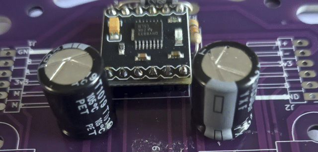
Next, we will add the two 100uF electrolytic capacitors C3 and C4. Note that both of these are polarised and MUST go in the right way round. The lead on the grey side of the capacitor with the minus sign on it goes in the hole shown white on the printing on the board. Note that the left one of these has the negative side pointing forward and the other has the negative side pointing backwards as shown here. You capacitors may be smaller than these shown depending on the voltage rating and source. Solder both of them on the bottom of the board.
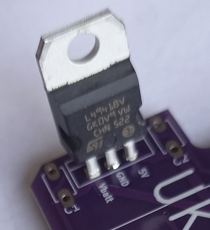
Next we will add the 5Volt regulator U2. Put it in so that the flat side is on the outer edge of the board and the black section is towards the labels for 5V, GND and Vbatt. Solder it on the bottom of the board.
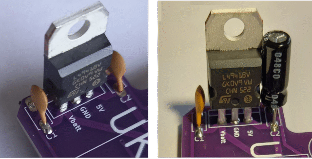
Depending on the device used you will have different capacitors on either side of it. If you are using the LM7805 you will have a 0.22uF capacitor for C1 and a 0.1uF capacitor for C2. These can be inserted either way round. But if you are using the L4941BV regulator you will have a 0.1uF capacitor for C1 and a 22uF electrolytic capacitor for C2. The two options are shown below. If you have the 22uF electrolytic capacitor C2 on the right it should be inserted so that the negative stripe is at the edge of the board and the positive side towards the middle of the board.
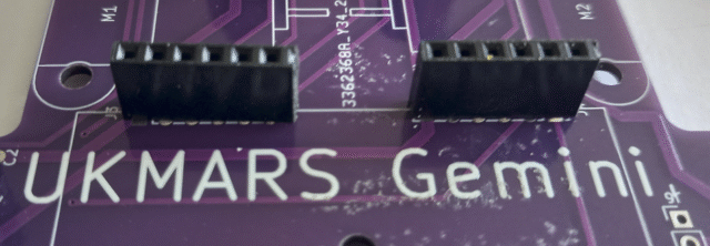
Next add the two 6 pin sockets that will connect to the Mezzanine board. If you have a longer strip of sockets, cut them at the 7th socket, which will leave 6 clean sockets to put on the board. Solder one end in first then check that they are fully seated squarely on the board before soldering in the other 5 pins. Repeat for both 6 pin sockets.
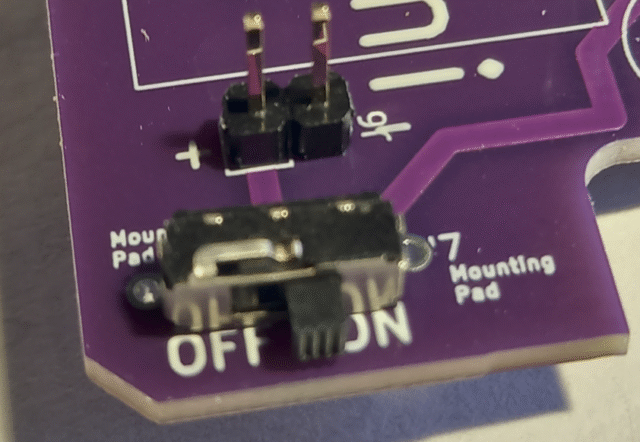
Next we will add the on/off switch and battery connector. The on/off switch may just have 3 pins as this one shown or it may also have 2 extra pins used to give extra support to the switch at each end. If you only have 3 pins on your switch, solder it into the middle 3 holes leaving a mounting pad hole at each end. Then add the 2 pin battery connector. Several different 2 pin styles can be used or you can even just solder the battery lead directly into the board. If you do this, give it some extra support such as some hot glue around it to stop it being pulled and broken. A simple unpolarised 2 pin connector is shown here.
Next we add the motor and encoder connectors J1 and J2 These are two 6 pin angled connectors which connect the 2 motor power leads and the 4 encoder leads. If you are not putting motors with encoders on your robot you only need to connect the 2 motor power leads marked M+ and M- You could solder the motor power leads directly into these or just use a 2 pin angled connector for each side. Both full 6 pin angled connectors are shown below.
Your main chassis board is now ready to add the motors.
The Mezzanine Board
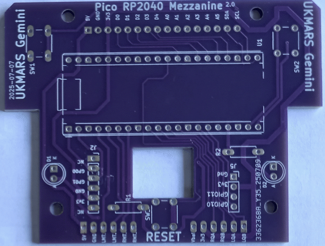
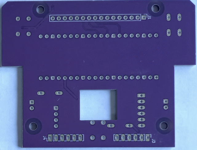
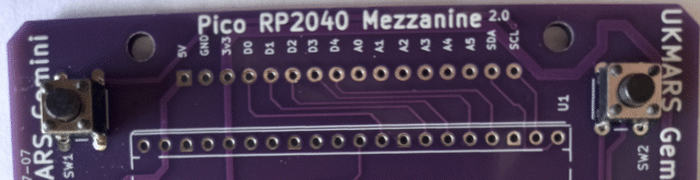
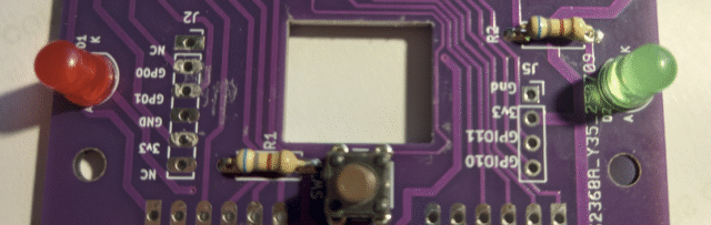
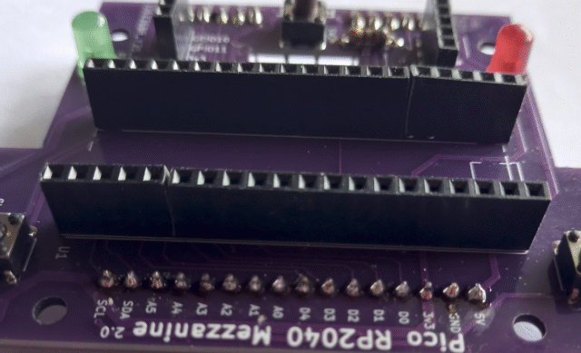
This is the top of the Gemini V2 Mezzanine board for the Raspberry Pi Pico RP2040 processor.
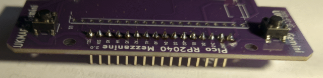
And this is the bottom of the Mezzanine board for the Raspberry Pi Pico RP2040 processor.
There are only a few components to be added other than connectors. We will start by adding the 3 tactile switches SW1, SW2 and SW3 the RESET button. They will only go in one way round so carefully align the pins on then and push then through so as to fit flush on the board, then solder them in. Here are the positions of tactile switches SW1 and SW2 at the front of the board.
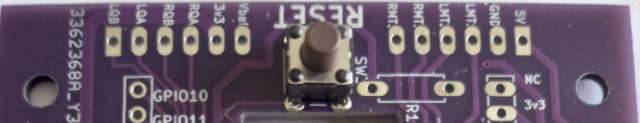
This is followed by tactile switch SW3 on the back of the board next to the word RESET
Next are R1 and R2, the 680 ohm (coded green, grey, brown) LED load resistors.
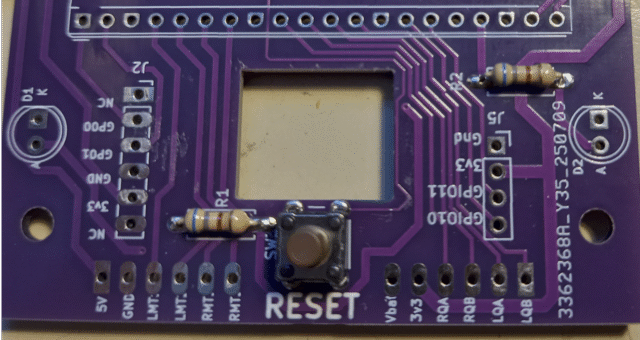
Note also the position of LEDs D1 and D2 which are marked K(for cathode) and A (for Anode) in the image above. The long lead goes in the side marked A and the short lead goes in the side marked K. Two different colour LEDs are recommenced as shown below. Do not use blue or white ones as they require higher voltages so may not work.
Now we are ready to add headers and sockets. The sensor board connector at the front of the board uses a 16 pin header. It is put in on the underside of the board and hence soldered on the top surface as shown.
Then add the two breakout sockets J2 and J5. J2 is a 6 pin socket and J5 is a 4 pin socket. Solder them on the bottom of the board next to the LEDs as shown.
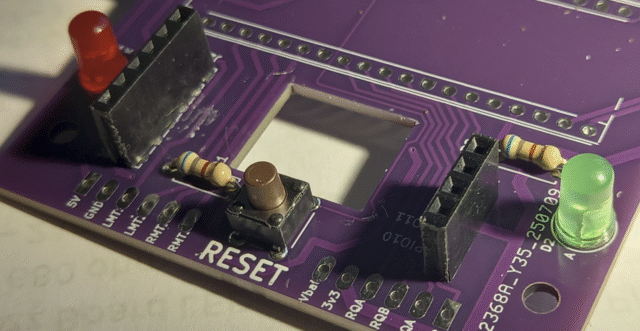
Now add the two 6 pin connectors which go below the board and are soldered on the top of the board. They are either side of the RESET tactile switch.
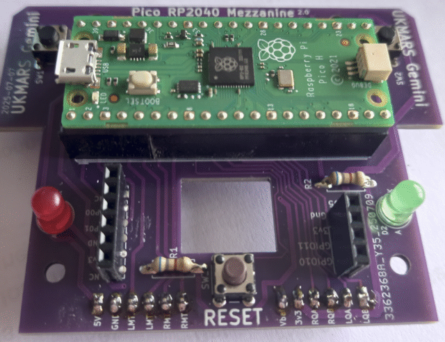
If your Pico Processor board is to be socketed, add the two 20 pin sockets for that,
Putting the Pico into the socket means that it will now look like this: Make sure that it is put in so that the USB micro socket matches the square shown on the screen print and next to tactile switch SW1
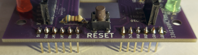
Then finally add the two 6 pin extra long pin spacers that will connect the mezzanine board to the main chassis. These go between the mezzanine board and the main chassis board and plug in to both. First plug the pin ends into the main chassis J4 and J5 sockets
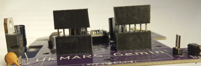
Then plug the mezzanine board into the sockets
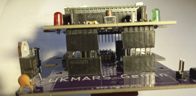
You should now have almost an inch (23mm) between the chassis and mezzanine boards and 3mm of 6 connector pins showing between the connectors on each of the sockets.