This page describes how to build the line sensor mini that shines the sensors through the v1.3 main board when using it with a python based RP2040 CPU that only has 4 Analogue to Digital converter inputs. There is also a separate board specifically for use with the Cytron Maker Nano RP2040 which also has a TV remote receiver on it. This is described further down the page after the build using the standard line sensor.
The normal build for the Arduino Nano CPU has 4 central line sensors plus the 2 side marker sensors. For this build we will just use 2 of the central line sensors plus the 2 side marker sensors. The RP2040 CPU runs at 3.3 volts, so we will adjust some of the normal resistor values. Also, because we are using less LEDs at a lower current we will use just one transistor to switch the LEDs instead of two.
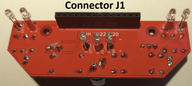
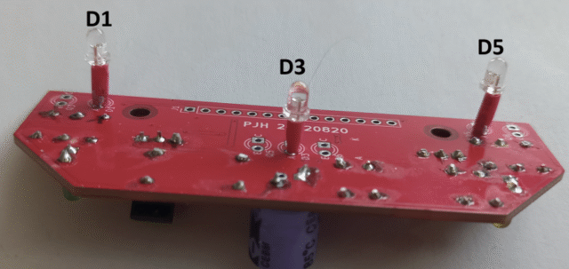
The image shows the top view of the reduced build needed
Here are the build instructions for the components mounted on the top of the board. Start with adding 2 plain wire connections. The first one replaces R1 and the second connects the collector (C) of Q2 to the cathode(K) of D2. Next add the 3 LED resistors R3, R5 and R6 using 33 ohm values (marked orange, orange black). Then add the 4 phototransistor resistors R11, R13, R14, and R16 using 2.2k ohms values (marked red, red, red). Next add the indicator LED resistors R26 and R27 using 220 ohm values (marked red, red, black) then the 2 indicator LEDs D6 and D7 (shown here yellow and green). Next add the two transistor bias resistors R7 value 390 ohms (marked orange, white, brown) and R8 value 10k ohms (marked brown black orange). You can now add the transistor Q1 making sure the outline matched the shape of the device. Finally, but not shown, add the 470uF capacitor C1 with the negative side on the white area. Finally, cut the track that goes to A5 at the edge of the board below the 5V connector.
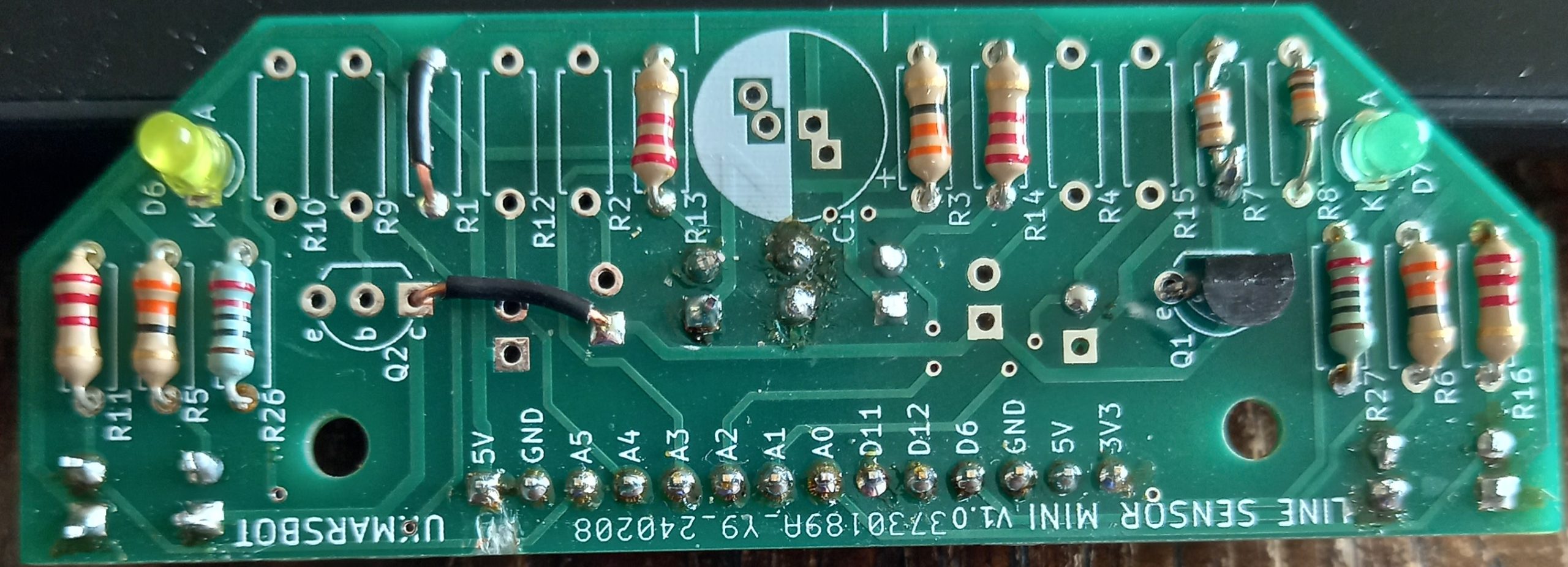
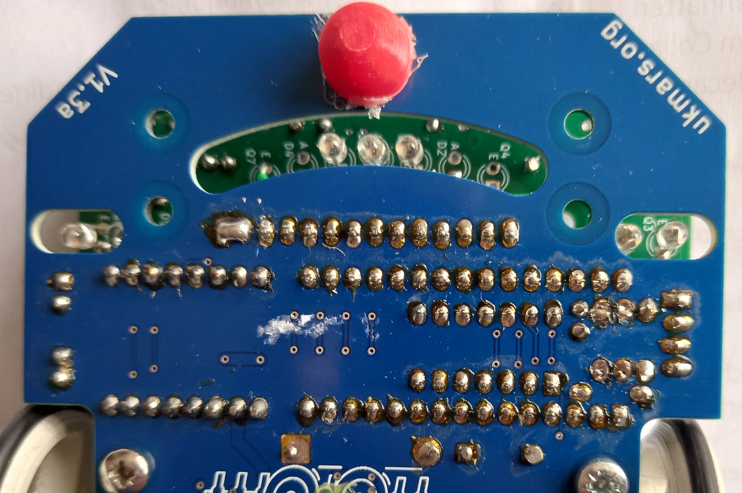
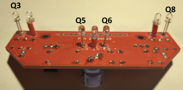
This image shows the bottom of the build showing the LEDs and phototransistor sensors
Here are the build instructions for the components mounted on the bottom of the board. Start with adding a plain wire connection from the emitter of Q7 to the bottom end of R7. Then add the 3 illumination LEDs D1, D3 and D5. Make sure the longer leads on the LEDs go into the anode (A) hole. Let the base of the LEDs stand about 5mm off the board as shown in the image below. Add the 4 phototransistors Q3, Q5, Q6 and Q8. If using the recommended BPW85 devices the long lead should go in the emitter(E) hole. Finally add the 14 way J1 connector.
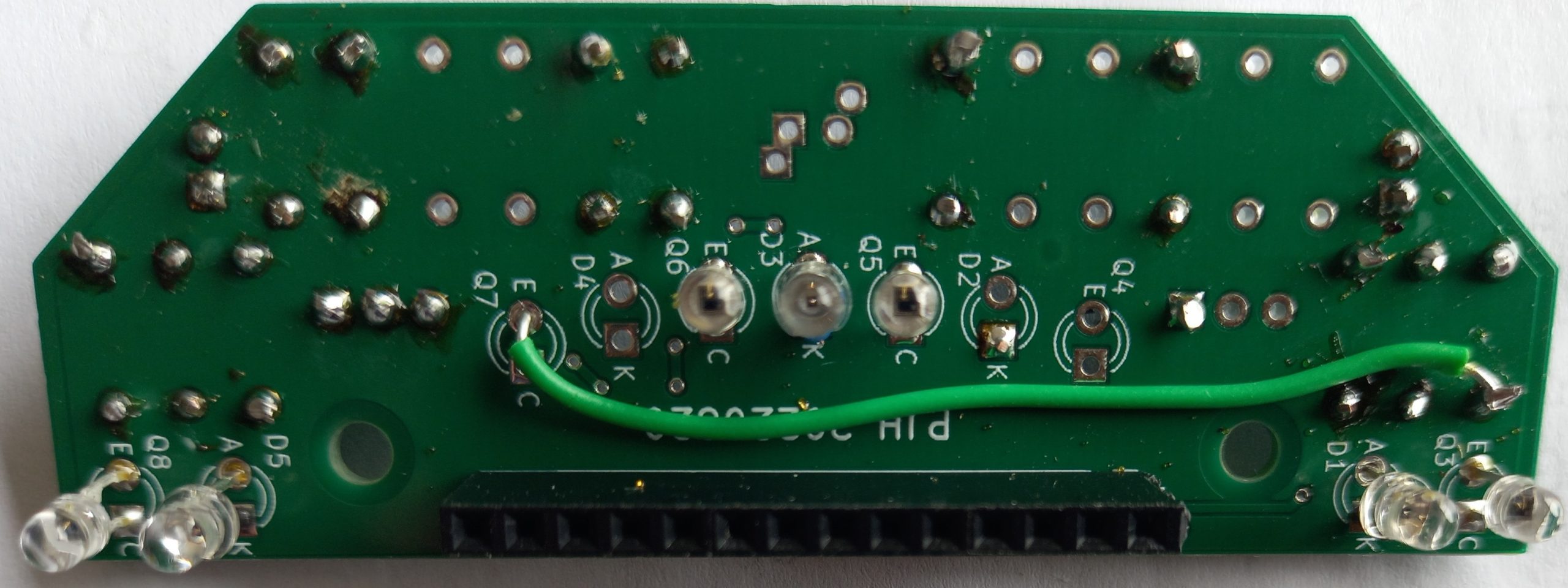
This view shows the sensors at a better angle to see the length of the leads on them and also the J1 connector
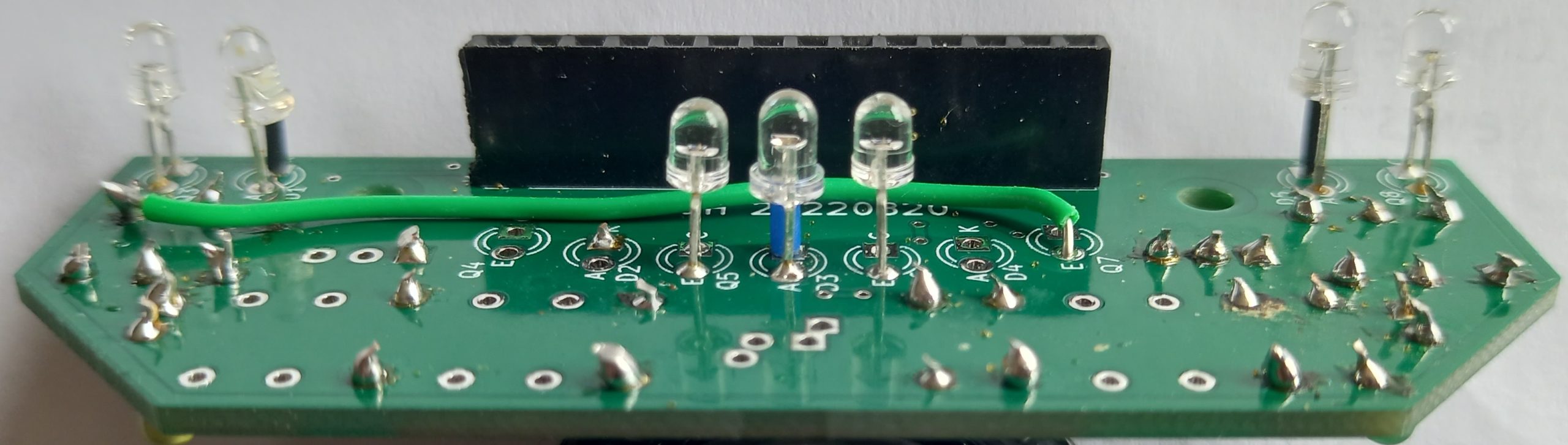
and this shows how the sensors shine through the slots in the front of the main board
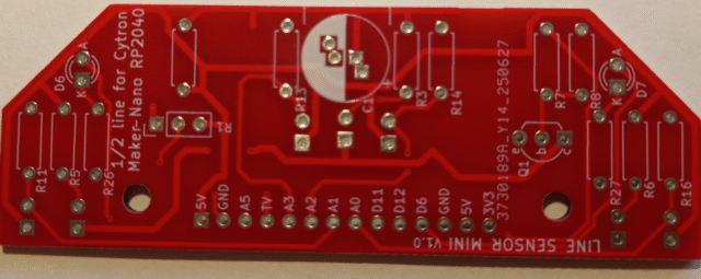
Cytron Maker Nano RP2040 1/2 width line board
This is the top view of the board – Note that it says “1/2 line for Cytron Maker Nano RP2040” on it
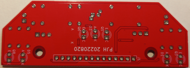
This is the bottom of the board – It is labelled PJH 20220820 – Ignore that, it is a July 2025 design
Here is the parts list:
Resistors – R3,R5, R6 33Ὠ; R7 390Ὠ; R8 10KὨ; R11, R13, R14, R16, R26, R27, 2.2KὨ
Transistor – BC337-40 Bipolar NPN transistor- Rapid-online Order code: 50-3113
Capacitor – C1 470µF low impedence 10V electrolytic – Rapid-online Order code: 11-3664
Emitter LEDs – 3 x Truopto OSHR3131A-NO 3mm 3000mcd – Rapid-online Order code: 55-0066
Phototransistor – 4 x Vishay BPW85C 3mm – Farnell part no 104-5380 08
Indicator LEDs – 2 x Any general purpose visible LEDs
Connector – 14 way single row male header- Rapid-online Order code: 01-5841
Infrared TV remote receiver (optional item) – Vishay TSOP4838 Rapid- online Order Code: 55-0905
Build Sequence
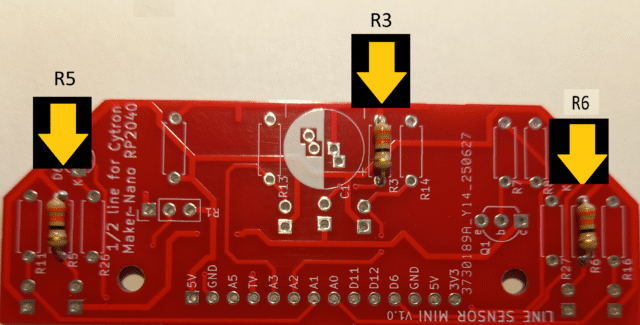
Start by adding the three 33Ὠ LED limiter resistors R3, R5 and R6.
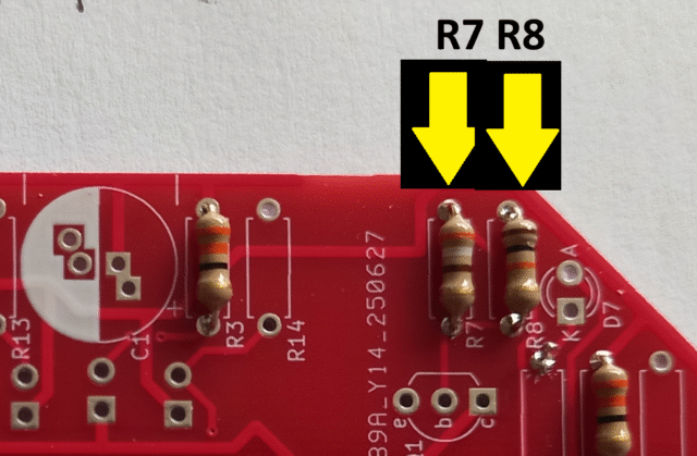
Then add the two transistor bias resistors R7 390Ὠ and R8 10KὨ
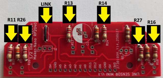
Then add the four phototransistor load resistors and the two indicator LED resistors R11, R13, R14, R16, R26, R27 all at 2.2KὨ, plus a zero ohm link wire as shown. This link wire position is there if you want to add a further limiting resistor for the LEDs but is not needed when running at the 3.3Volts supplied by the Cytron board.
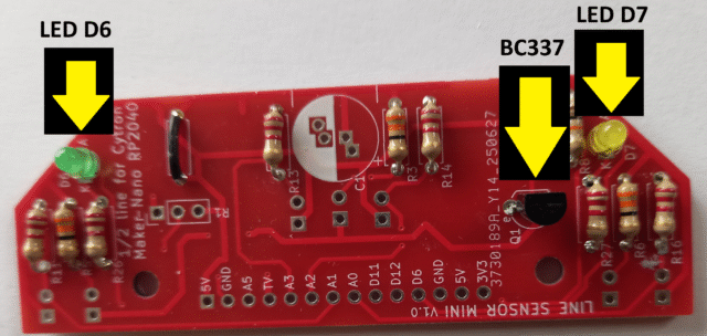
Next solder the BC337-40transistor in, with the flat side as shown on the silk screen. Then add the 2 small indicator LEDs. Choose 2 different colour LEDs such as green, red or yellow, but not blue or white as the voltage available may not be high enough for those colours. Put the long lead of the indicator LEDs in the holes marked A (for Anode) at the front edge of the board, and the short lead in the hole marked K (for Cathode).
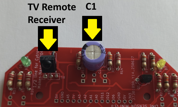
Finally, for the last main item on the top of the board add the 470µF C1 capacitor, with the negative side lead going into the white area shown on the board, and the positive side lead going into the red area. Two holes are provided to cater for different sized items. The capacitance value is not critical as long as it is over 100µF, but the higher the better to smooth out any supply ripples.
We have one optional item to add if required. This is the Vishay TSOP4838 infrared TV remote receiver. Insert the 3 leads so that the raised lens is facing to the back of the board where the main board connector is. Allow about 5mm of leads above the board and after it is soldered in, bend it back by about 45 degrees over the link.
Now we will add the items on the bottom of the board, the three LEDs, four phototransistors and the main board connector
Put the high brightness red LEDs D1, D3 and D5 in to the bottom of the board with the long lead in the hole marked A (for Anode), then solder them on the top. Allow about 4mm of component lead between the LED and the board. Use a spacer on one lead to get the correct height, then solder one lead. Check that the LED is standing upright and adjust it if needed before soldering the other lead. By trying to straighten it after both leads are soldered you may pull off the PCB pads and spoil the board.
Now put in the four BPW85C phototransistors Q3, Q5, Q6 and Q8. The longer lead goes into the hole marked E (for Emitter)
Finish this side by soldering in the 14 way connector. Your board should now be complete.