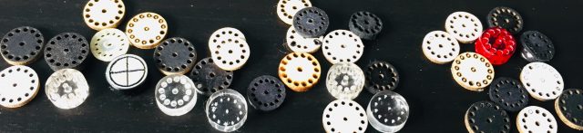
This post is intended to add detail to the manufacturing/assembly process of a Magnetic Encoder disk for use with Pololu Hall Effect circuit boards, and in the future, our own boards. By sharing what I have discovered, I hope to speed up the process for others wanting to make such a disk, without them having to create a large collection such as this first…
Encoder Disk Design
The Encoder Disk design evolved through several iterations, the latest of which is shown below. The Grey area is the intended shape of the Encoder, the Red lines show the laser tool path. Each hole in the disk is cut in two stages (inner first), this ensures a clean separation between disk and offcut – because I soon realised that life is too short to have to poke the middle out of each hole!
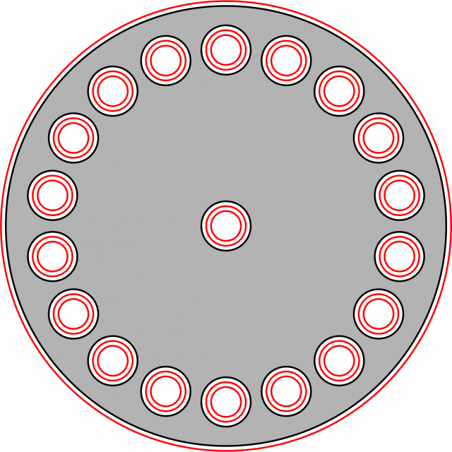
NB. Inherent to the Laser cutting process is that the laser cut is not infinitely narrow, the effective width of cut is called ‘Kerf’. For my Laser cutter, materials and speed/power used, I found Kerf to be approximately 0.2mm, hence the toolpath follows a 0.1mm contour around the part.
Manufacturing Encoder Disk
Laser cutters and accompanying software transform CAD data into position/speed data from an input file, in this case, the red lines as shown above. I changed the cut order to cut from the inside first, this reduces the risk of the part moving until the very end of the process. Below is a video showing the Laser cutting Black ‘Mounting Board’.
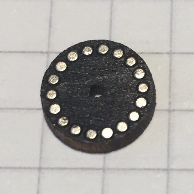
The resulting disk comes from the process in a condition ready for magnet insertion.
Material Consideration
Encoder Disk material selection became a balance of three main things:
1) Ability to cut on a laser (Some materials are toxic)
2) Pliable enough to accept magnet insertion
3) Sturdy enough to maintain shape and alignment on shaft
The table below shows materials that were tested and the findings. They are listed in order of what I considered most plausible.
| Material | Laser Notes | Accepts Magnet Insertion | Grip on Shaft |
| 1.6mm Balsa | Fast, with little charring | Yes – very repeatable press fit | Average – would require strengthening |
| 1.25mm Mounting Board | Fast, with little charring | Yes – very repeatable press fit | Average – would require strengthening |
| 2mm MDF | Slow with large amount of charring | Yes – less compliance than above materials | Reasonable |
| 3mm Acrylic | Moderate speed, great edge finish | No – Push fit tolerance could not be achieved – either magnet would not go in or it would fall out | Same problem as magnet insertion |
| 1mm Nylon | Melts – leaves burrs | N/A | N/A |
After trials in all of the aforementioned materials, I settled on the use of Balsa Wood, for its speed to produce and ability to ‘give’ enough to accept magnets easily. Of course, this same property (compliance) is a slight disadvantage for the connection to the motor shaft. As Pete Harrison mentioned in his post here, this can be overcome with the application of either CA glue or nail varnish to the disk to harden it.
Encoder Assembly
The Encoder may be easily assembled with a tool comprising of cocktail stick with magnets glued on each end secured with heat-shrink. The polarity of the magnets is different, and identified with different coloured heat-shrink.
I created a video to show how the tool could be used to install magnets into a disk. This was a development disk with only 14 magnets, but the same principle applies for any number of magnets.
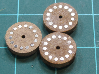
The resulting disk once assembled: