
I wanted to build a UKMARSBOT line follower but code it in Python. So here I describe how to replace the Arduino Nano with the recently launched Raspberry Pi Pico.
The Pico is not ideal in many respects, particularly because it only has 3 A to D ports, where we normally use up to 6 on the UKMARSBOT – 4 for sensors, one for battery voltage monitoring and one for the 4 pole mode selection switch. However it can be made to do a line follower if you don’t mind losing the use of the mode switch..
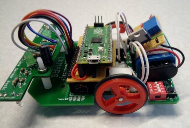
The basic approach is to make an interface board that plugs in where the Nano would normally go, and this acts as a carrier and connector for the wider and longer Pico. In addition, because the Pico requires a regulated 5V input we need to add a mini power supply board on top of the battery to feed 5 Volts into the UKMARSbot instead of the typical 7 to 9 volts.
This what it looks like:
And here is a link to a youTube video of the robot line following round a simple oval test course Pico UKMARSBOT
To install python on the Pico go to this link Pico getting started and follow the instructions to download the UF2 file onto your Pico. The best way of using the Pico in python is with Thonny application (available for free at https://thonny.org/) You need to use the latest version – at least version 3.3.3 for Pico support. Note that if you already have Thonny installed on your development machine it may install in another place and not update any shortcuts you have. On my Windows 10 PC I had to set up a new shortcut to the new location. You also need to go into Thonny Tools then Options then the interpreter tab then select MicroPython (Raspberry Pi Pico) and then with the Pico plugged into a USB socket, select the Port
You should now be able to write micro python programs in Thonny, and when you choose “save as” it willl give you the option to save it either on your development machine or onto the pico.
You can use the stop and run buttons in thonny to run the program on the pico, and if you include print statements for diagnostic purposes these will print on your development machine in the console section of Thonny below the code
If you save your program as main.py on the pico it will automatically run when you power up the pico without the USB connected.
So what is different with micro python? First point to note is that when you set up an input or output pin using a micro-python statement such as led = Pin(25, Pin.OUT) the PIN number used refers to the GP number not the physical pin number. Here is a link to a text file that contains a simple line following program which demonstrates the use of pin assignments, analogue input and PWM output Python line follower code
Now in terms of using the Pico on the UKMARSBOT chassis there are a few things to do : Firstly, we need to provide a 5V power source for the Pico. Normally on UKMARSBOT we use a 9v battery for power and let the Arduino Nano generate the 5V line that we use. So instead, we will use a simple 5v regulator on a small board that sits on top of the battery and feed this 5 volts into the battery input instead. Any 5v regulator of an amp or more should be OK but remember to put a switch in the feed from the battery as the normal on/off switch on the UKMARSBOT will be after the regulator now.
Secondly, remember that the Pico only accepts 3.3v inputs not 5 volts, so if you have a line follower or wall sensor board attached you need to change the input to this to use the 3.3 volt line instead of the 5v line. All you have to do is to move the plug in connection at the front of the board over one pin to use the last pin marked 3v3 instead of the one next to it marked 5v. The board will work just fine at 3.3 volts but the LEDs will not be quite as bright, but still plenty bright enough for line following.
Thirdly, we need to make an interface board to be able to plug in the Pico, as it is wider and longer than the Nano. I used a piece of vero-board with 2 rows of 15 pins matching the Nano socket on one side and 2 rows of 20 pin inline sockets on the top to match the wide and longer Pico. Note that depending on what motor brackets you are using and if you have encoders on the back shaft of the motors you may need to elevate the interface board higher with longer connector pins so that it clears the motor brackets and encoders. Alternatively, as not all the pins are used on the motor side of the Pico you can reduce the board size on that side to clear the motor brackets. This may mean that some of the Pico pins don’t connect with anything, but these should all be pins that we are not using. Start off by making sure that there are NO connections between the Nano pins and the Pico socket pins. If you put the Pico on the vero-board the other way round to the normal Nano orientation i.e. so that the USB micro connector on the Pico is on the side away from the motor driver board you will find that most of the pins that we need to connect up are close to where we want them to be. Using the table in the word document at this link connect up the pins as needed: UKMARSBOT pico pin connections
Most of the connections will be either adjacent to or only one or two pins away from where needed so some short connecting wires on the vero-board will do this. If you are making a PCB to do this then the pins are placed for easy connection.
Fourthly, the connections above are the minimum to make the robot line follower work and use one indicator LED on the main PCB. If you want to connect up the encoders remember that they produce a 5 volt output so we will need 2 signal level adjuster resister on each input to bring the inputs down to 3.3v or less. A 2.2 K resistor in series with a 1k resistor will work fine. Put the 2.2k end to ground, the other end to the 5 volt signal from the encoder and take the output from the junction between the 2.2 and 1k resistors to feed into the Pico.